
A Method for Suppressing Hole Clogging Effect of Vacuum Filter Using Nearly Uniform Magnetic Field

A technology of uniform magnetic field and filter, which is applied in large-scale high-power pulse laser devices and the field of plasma, can solve the problems of high-power pulse laser compression process, inability to filter perfectly, low cut-off frequency, etc., and achieve simple debugging and practicability Strong, easy-to-maintain effect

Active Publication Date: 2018-04-13
SHANGHAI INST OF OPTICS & FINE MECHANICS CHINESE ACAD OF SCI
View PDF7 Cites 0 Cited by
  • Summary
  • Abstract
  • Description
  • Claims
  • Application Information

AI Technical Summary

Problems solved by technology

The "blocking effect" of the traditional vacuum filter refers to the plasma generated by the interaction between the "skirt" of the high-power pulsed laser and the edge of the small hole due to free diffusion to the center of the small hole, blocking the high-power pulsed laser The trailing edge of the pulse continues to pass through the small hole, making the traditional vacuum filter unable to filter perfectly
[0006] Chinese patent 201320775747.5 discloses a spatial filter with a low cut-off frequency. Although the utility model patent can reduce the plugging effect of the traditional vacuum filter by installing a Bragg volume grating in front of the traditional vacuum filter, the Bragg volume grating used in this patent The grating not only has a low damage threshold, but also has the problem of its own size limitation
This is not suitable for large traditional vacuum filters with large laser spots and high energy density of injected lasers, and installing Bragg volume gratings in front of traditional vacuum filters will introduce certain aberrations, which is not suitable for subsequent compression of high-power pulsed lasers. The process will have additional effects

Method used


Image

  • A Method for Suppressing Hole Clogging Effect of Vacuum Filter Using Nearly Uniform Magnetic Field
  • A Method for Suppressing Hole Clogging Effect of Vacuum Filter Using Nearly Uniform Magnetic Field
  • A Method for Suppressing Hole Clogging Effect of Vacuum Filter Using Nearly Uniform Magnetic Field

Examples


Embodiment Construction

[0034] The present invention will be described in detail below in conjunction with the accompanying drawings and specific implementation examples.

[0035] In order to achieve the purpose of suppressing the plugging effect of the traditional vacuum filter, the invention proposes a method of using a nearly uniform magnetic field to act on small holes.

[0036] The specific implementation mode is summarized as follows:

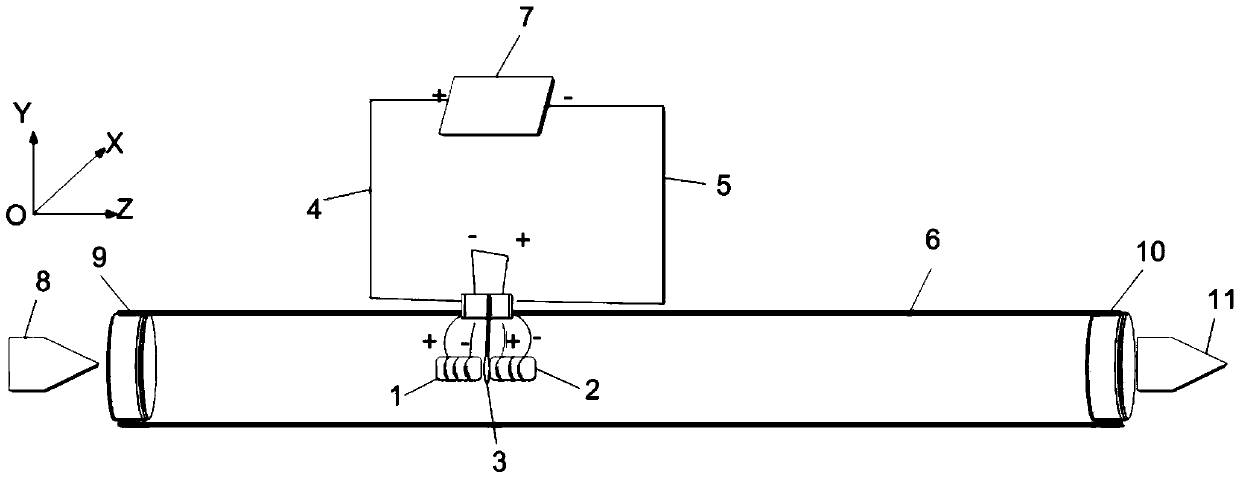
[0037] Step 1. Taking the cross-section of the small hole in the vacuum filter as the XY plane, fix the first hollow coil 1 and the second hollow coil 2 with the same specification parameters as the first hollow coil 1 on the vacuum filter along the Z axis The front and rear ends of the small and medium hole 3 make the direction of the magnetic induction line of the nearly uniform magnetic field perpendicular to the XY plane;

[0038] Step 2, lead the first wire 4 connected to the positive pole of the first hollow coil 1 to the outside of the vacuum filter 6 an...


PUM


Abstract

The invention relates to a method for inhibiting the hole blocking effect of a vacuum filter using a near uniform strong magnetic field. The method is used for solving the problem of existing traditional vacuum filter that complete filtering is unavailable since the free-diffusion metal plasma generated by the focal spot wing (hereinafter called 'skirt') after focusing of high-power pulse laser acting on the edge of a filtering component (hereinafter called 'small hole') hinders the passage of the back edge of the laser pulse. In the invention, based on traditional vacuum filter, a near uniform strong magnetic field with certain magnitude is applied to the small hole, the metal plasma generated on the edge of the small hole by the focusing skirt of the high-power pulse laser moves in the direction of magnetic induction line, thus the plasma density at the center of the small hole is reduced, the hole blocking effect of traditional vacuum filter is effectively solved, and a good filtering effect of traditional vacuum filter is realized. The method provided by the invention has the characteristics of convenience in adjustment, simplicity and high efficiency, high practicability and the like.

Description

technical field [0001] The invention relates to the field of large-scale high-power pulsed laser devices and the field of plasma, in particular to a method for suppressing the hole blocking effect of a traditional vacuum filter. Background technique [0002] In the field of high-power pulsed laser devices, the inhomogeneity and small-scale self-focusing effect of amplifiers at all levels in the pump light and signal light have become the main reasons affecting the quality of the near-field beam, so the uniformity of the laser near-field spot can be improved. Performance plays an irreplaceable role in improving the load capacity of high-power pulsed laser devices. [0003] In the past few years in the research of petawatt-level high-power pulsed laser devices, despite the gradual improvement of the beam quality of pump light and signal light at all levels, the gradual improvement of the damage threshold of various optical components and the corresponding AO active compensatio...

Claims


Application Information

Patent Timeline
Patent Type & Authority Patents(China)
IPC IPC(8): G02B27/46
CPCG02B27/46
Inventor 李文启梁晓燕於亮红郭震彭纯李儒新
Owner SHANGHAI INST OF OPTICS & FINE MECHANICS CHINESE ACAD OF SCI
Learn More