Terminal crimping and shell plugging device for full-automatic wire stripping terminal crimping and shell plugging machine

A fully automatic, plugging machine technology, applied in the assembly/disassembly of contacts, circuit/collector parts, electrical components, etc., can solve problems that are not suitable for large-scale and intensive production, low work efficiency, and high labor intensity and other problems, to achieve the effect of high degree of automation, high work efficiency and smooth operation

Inactive Publication Date: 2016-06-08
宗智辉
View PDF6 Cites 3 Cited by
  • Summary
  • Abstract
  • Description
  • Claims
  • Application Information

AI Technical Summary

Problems solved by technology

[0004] The existing disadvantages of this technology are: manual operation is very cumbersome, low production efficiency, and labor-intensive for short-length wires.
In addition, because there are too many wires between electronic components and circuit boards, and the current processing procedures are basically done manually, the work efficiency is extremely low, so that it is not suitable for large-scale and intensive production at all. Therefore, it is urgent Relevant automation equipment in the production department is required to improve work efficiency and reduce labor intensity

Method used


Image

  • Terminal crimping and shell plugging device for full-automatic wire stripping terminal crimping and shell plugging machine
  • Terminal crimping and shell plugging device for full-automatic wire stripping terminal crimping and shell plugging machine
  • Terminal crimping and shell plugging device for full-automatic wire stripping terminal crimping and shell plugging machine

Examples


Embodiment Construction

[0027] The present invention will be further described below in conjunction with specific embodiments and accompanying drawings.

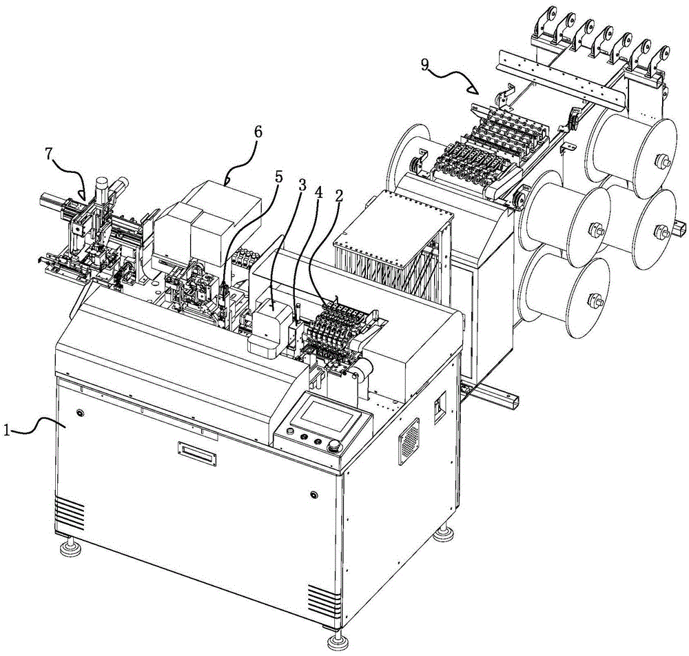
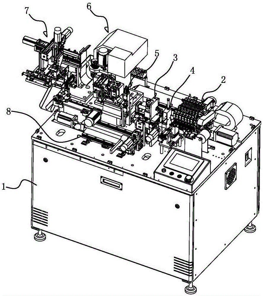
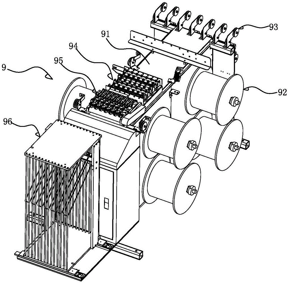
[0028] See Figure 1-10 As shown, it is a fully automatic wire stripping and plugging machine equipped with the present invention, which includes: a machine base 1 and a front end XY axis wire feeding device 2 installed on the machine base 1, a front end wire stripping and twisting device 3. Flux dipping device 4, rear-end wire stripping device 5, end-stripping device 6, three-axis plug rubber shell device 7, rear-end wire feeding device 8 and installed on the side of machine base 1 and sent to the front XY axis The wire device 2 is docked with the wire feeding device 9, wherein the end device 6 and the three-axis plug shell device 7 constitute the end plug device of the present invention (ie, the present invention).

[0029] The front-end XY-axis wire feeding device 2 includes an XY moving base 21 installed on the machine base 1, and several grou...


PUM


Abstract

The invention discloses a terminal crimping and shell plugging device for a full-automatic wire stripping terminal crimping and shell plugging machine. The terminal crimping and shell plugging device comprises a terminal crimping device and a three-axis rubber shell plugging device, wherein the terminal crimping device comprises an terminal crimping mechanism and a dual-track translation feeding mechanism, wherein the terminal crimping mechanism is installed on a machine base of the full-automatic wire stripping terminal crimping and shell plugging machine, and the dual-track translation feeding mechanism is installed on the terminal crimping mechanism. The three-axis rubber shell plugging device is installed on the machine base and located on the side of the terminal crimping device. The dual-track translation feeding mechanism is located above the rear-end feeding device and comprises a first installation frame, a first track, a second track, sliding blocks, feeding arms and a motor assembly, wherein the first installation frame is installed on the terminal crimping mechanism, the first and second tracks are installed on the first installation frame, the sliding blocks are installed on the first and second tracks, the feeding arms are installed on the sliding blocks and vertically distributed, the motor assembly is installed on the first installation frame and used for driving the feeding arms to translate in the direction of the first track and the second track, and material clamps are arranged at the lower ends of the feeding arms. The terminal crimping and shell plugging device is high in automation degree, smooth in operation, high in working precision, high in efficiency and good in quality.

Description

Technical field: [0001] The invention relates to the technical field of wire processing, in particular to an end plugging device for a fully automatic wire stripping and plugging machine. Background technique: [0002] The current electronic products all involve the cable connection between the electronic components and the circuit board. The cable can be directly plugged and used, which is very convenient to use. The flat cable includes a plastic case and a plurality of wires fixed to the plastic case, wherein one end of the wire is provided with solder, and the other end is provided with a terminal, and the terminal is plugged in the plastic case to form a flat cable. [0003] In the prior art, the production of such cables is basically manual operation: cut the wires to a specified length, then strip the two ends of the wires to expose the wires, and then tighten the exposed ends of the two ends of the wires , and then dip one end of the wire into tin liquid, then make a...

Claims


Application Information

Patent Timeline
Patent Type & Authority Applications(China)
IPC IPC(8): H01R43/05H01R43/052H01R43/20
CPCH01R43/05H01R43/052H01R43/20
Inventor 宗智辉
Owner 宗智辉
Why Eureka
Try Eureka