High-power capacitor boost power supply
A booster circuit, capacitor technology, applied in output power conversion devices, DC power input conversion to DC power output, electrical components and other directions, can solve the problems of generating magnetic fields, generating electromagnetic fields, and difficulty in reducing the size of inductance, and achieve broad development. Foreground effect
- Summary
- Abstract
- Description
- Claims
- Application Information
AI Technical Summary
Problems solved by technology
Method used
Image
Examples
Embodiment
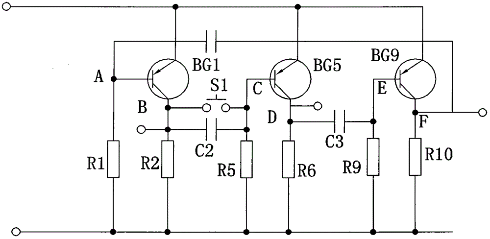
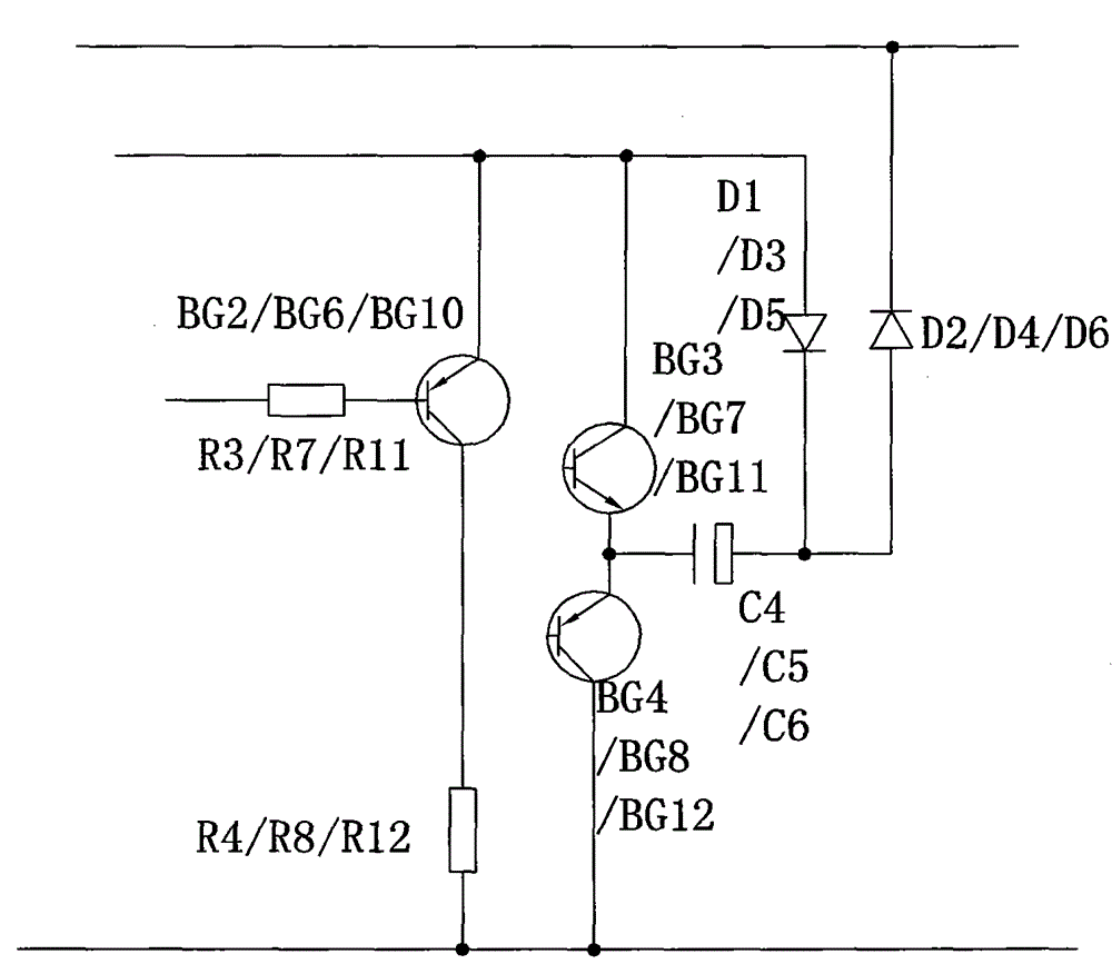
[0026] according to Figure 6 The parameters in, R1, R3, R5, R7, R9, R11 are all 10Ω resistors, R2, R4, R6, R8, R10, R12 are all 1Ω resistors, C1, C2, C3 are all 0.02μF capacitors, C4, C5 , C6 are 470μF capacitors. Diodes D1, D2, D3, D4, D5, and D6 use 1N5819 diodes; triodes BG1, BG2, BG4, BG6, BG8, BG10, and BG12 all use 9012 triodes, and triodes BG3, BG7, and BG11 use 9013 triodes.
[0027] The frequency of the circuit oscillation is about 2kHz, which is much lower than the 100kHz of the traditional switching power supply, and it does not generate a magnetic field. This can greatly reduce the interference to the following circuit. As for the output capability, the larger the capacitor, the stronger the output capability. When using a 470μF capacitor, the circuit can provide an output capability of 500mA, which is 10W of power. However, the traditional capacitive boost circuit can only provide a current of a few milliamps or tens of milliamperes.
[0028]The characterist...
PUM
 Abstract
Description
Claims
Application Information
 - R&D
- Intellectual Property
- Life Sciences
- Materials
- Tech Scout
- Unparalleled Data Quality
- Higher Quality Content
- 60% Fewer Hallucinations
Browse by: Latest US Patents, China's latest patents, Technical Efficacy Thesaurus, Application Domain, Technology Topic, Popular Technical Reports.
© 2025 PatSnap. All rights reserved.Legal|Privacy policy|Modern Slavery Act Transparency Statement|Sitemap|About US| Contact US: help@patsnap.com


