
Stirring device for agent preparation

A stirring device and medicament technology, applied in the field of stirring tank, can solve the problems of inconvenient replacement and repair of stirring device, inconvenient movement of stirring device, influence on stirring efficiency, etc., and achieve the effect of improving stirring efficiency, convenient disassembly, and improving sealing

Inactive Publication Date: 2016-06-15
刘云海
View PDF5 Cites 17 Cited by
  • Summary
  • Abstract
  • Description
  • Claims
  • Application Information

AI Technical Summary

Problems solved by technology

[0002] In the production of medicines, raw materials are processed. The processing of raw materials often needs to be dissolved and crystallized. When dissolving, in order to make the dissolution efficiency faster, it will be stirred at the same time to make it dissolve faster. The traditional stirring device The kettle body is often integral, but later it was found that it was inconvenient to replace and repair the stirring device inside, so the method of combining the kettle body and the kettle cover appeared later, but the sealing performance of the combined stirring kettle is often affected. In addition, in the process of material dissolution, it is difficult to ensure that the material in the solution will not crystallize out. Once crystallization occurs, massive crystals will appear on the inner wall of the kettle. If they are not removed in time, the subsequent dissolution will not only It will have an impact, and it is troublesome to clean up, and if the ground is uneven when stirring, it will also affect the efficiency of the stirring, and the movement of the stirring device is also very inconvenient

Method used


Image

  • Stirring device for agent preparation
  • Stirring device for agent preparation

Examples


Embodiment Construction

[0016] The technical solution of this patent will be further described in detail below in conjunction with specific embodiments.

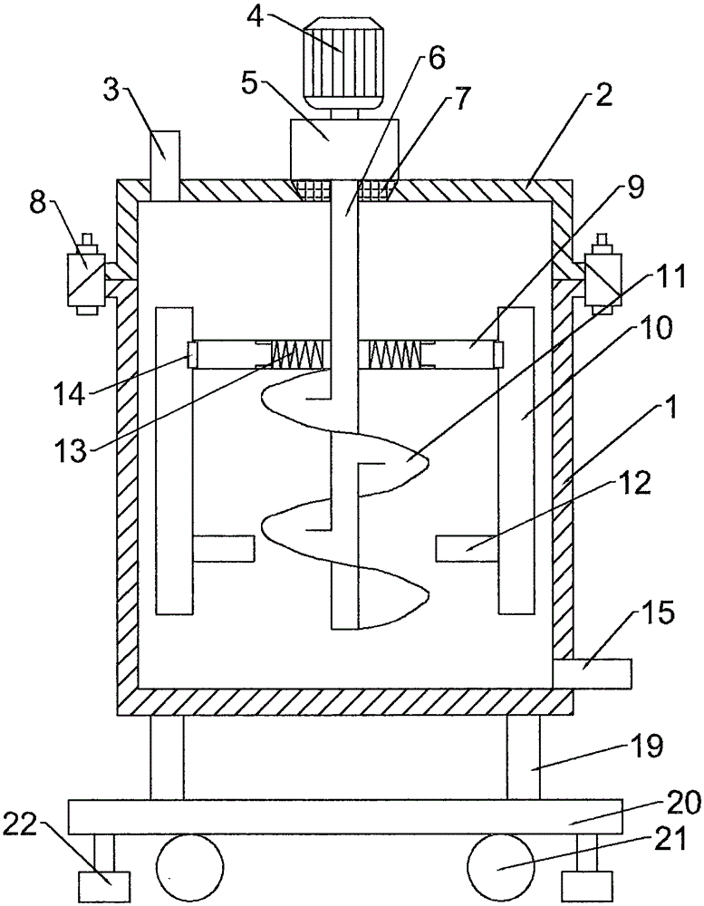
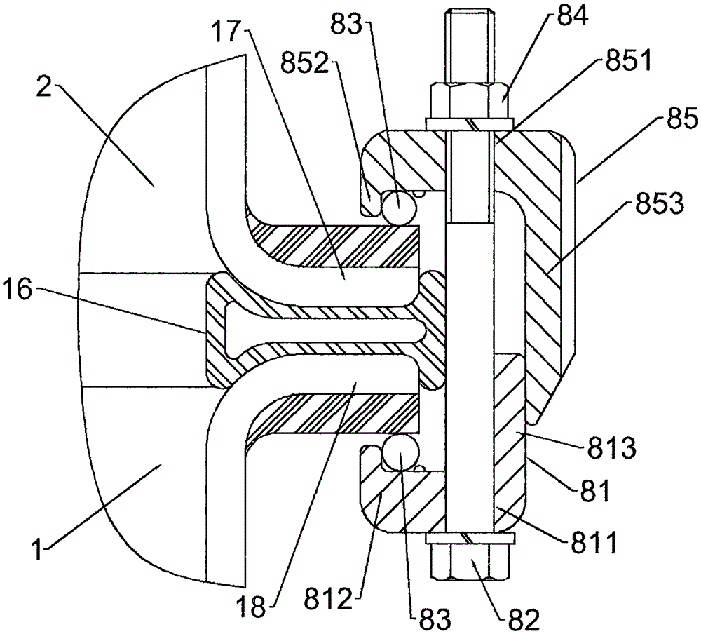
[0017] see Figure 1-2 , a stirring device for preparation of medicaments, comprising a kettle body 1, the upper end of the kettle body 1 is open, and a cover body 2 is provided at the opening, the upper end of the cover body 2 is provided with a feeding port 3, and a driving device is provided above the cover body 2 The lower end of the motor 4 and the driving motor 4 is connected with a deceleration mechanism 5, the output shaft of the deceleration mechanism 5 is connected with a rotating shaft 6 located inside the kettle body 1, a sealing mechanism 7 is provided at the connection between the rotating shaft 6 and the cover body 1, and the rotating shaft 6 is located in the kettle body 1 The lower part of the inside is vertically installed with a support rod 9, and the two ends of the support rod 9 extend to the inner wall of the kettle body 1 and...


PUM


Abstract

The invention discloses a stirring device for agent preparation. The stirring device comprises a still body. A cover body is arranged at the upper end of the still body in a matched mode. A drive motor is arranged above the cover body. The lower end of the drive motor is connected with a speed reduction mechanism. An output shaft of the speed reduction mechanism is connected with a rotating shaft in the still body. The lower section, in the still body, of the rotating shaft is vertically provided with a supporting rod. The two ends of the supporting rod are connected with scraper blades through elastic connecting pieces. A spiral blade is axially wound around the lower end of the rotating shaft. An upper flange is arranged on the cover body. A lower flange is arranged on the still body. The upper flange and the lower flange are connected through a clamping mechanism. A sealing gasket is arranged between the cover body and the still body. The clamping mechanism comprises a first clamping piece, a second clamping piece, a screw, a gasket and a nut. The supporting rod is arranged at the bottom of the still body. A bottom plate is fixedly connected with the bottom of the supporting rod, and wheels and lifting devices are arranged at the bottom of the bottom plate. Materials can be effectively prevented from being attached to a still wall, and stirring efficiency is improved; the sealing performance of the still body and the cover body is improved, and detachment and movement are convenient.

Description

technical field [0001] The invention relates to a stirring tank, in particular to a stirring device for preparing medicaments. Background technique [0002] In the production of medicines, raw materials are processed. The processing of raw materials often needs to be dissolved and crystallized. When dissolving, in order to make the dissolution efficiency faster, it will be stirred at the same time to make it dissolve faster. The traditional stirring device The kettle body is often integral, but later it was found that it was inconvenient to replace and repair the stirring device inside, so the method of combining the kettle body and the kettle cover appeared later, but the sealing performance of the combined stirring kettle is often affected. In addition, in the process of material dissolution, it is difficult to ensure that the material in the solution will not crystallize out. Once crystallization occurs, massive crystals will appear on the inner wall of the kettle. If the...

Claims


Application Information

Patent Timeline
Patent Type & Authority Applications(China)
IPC IPC(8): B01F7/16B01F15/00
CPCB01F27/054B01F27/072B01F27/073B01F27/114B01F27/17B01F27/112B01F27/805B01F2035/351B01F35/123B01F2101/22Y02P70/10
Inventor 刘云海
Owner 刘云海
Learn More