F-type rolling mill calibrating tool for hot continuous rolling production line

A rolling production line and rolling mill technology, applied in the field of calibration tools for F-type rolling mills in hot continuous rolling production lines, can solve problems such as inconsistent spacing L1, low copper bar usage, and potential safety hazards, and achieve improved accuracy and safety , Eliminate the effect of personal safety hazards

Inactive Publication Date: 2016-06-15
SHANDONG IRON & STEEL CO LTD
View PDF5 Cites 4 Cited by
  • Summary
  • Abstract
  • Description
  • Claims
  • Application Information

AI Technical Summary

Problems solved by technology

In order to ensure personal safety, every time personnel enter the rolling mill, they must first stop the power source and insert the safety pin, which will affect the normal production
Personnel go in and out of the rolling mill, frequently stop the power source, work efficiency is low, and there are potential safety hazards; the space is narrow, the length of the copper rod is required to be about 3.5m, and each rod can only be used 6 times, and the utilization rate of the copper rod is low; the copper rod is placed manually , the distance L1 between the two copper rods is inconsistent when they are pressed together, and the distance between the two copper rods and the rolling center line is inconsistent, which affects the accuracy

Method used


Image

  • F-type rolling mill calibrating tool for hot continuous rolling production line
  • F-type rolling mill calibrating tool for hot continuous rolling production line
  • F-type rolling mill calibrating tool for hot continuous rolling production line

Examples


Embodiment Construction

[0022] The features and principles of the present invention will be described in detail below in conjunction with the accompanying drawings, and the examples given are only used to explain the present invention, not to limit the protection scope of the present invention.

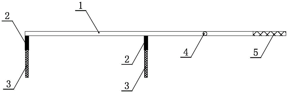
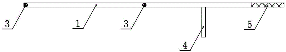
[0023] Such as Figure 1-4 As shown, the invention includes a support rod 1, a sleeve 2, a positioning rod 4 and a copper rod 3. The support rod is a slender rod, and two sleeves are fixed on the support rod. The two sleeves are equal in length and diameter, and the two sleeves are arranged in parallel.

[0024] The interval between the sleeves is L1, one end of the sleeve is vertically fixed on the support rod, the other end of the sleeve is open, and the copper rods are plugged in the open ends of the two sleeves, and the ends of the copper rods are exposed The sleeve is at a certain distance. The length and diameter of the two copper rods are also the same, and the distance between the two copper rods i...


PUM

PropertyMeasurementUnit
lengthaaaaaaaaaa

Abstract

The invention relates to an F-type rolling mill calibrating tool for a hot continuous rolling production line. The calibrating tool comprises a support rod, sleeves, a locating rod and copper rods, wherein the support rod is a long and thin rod piece, two sleeves are fixedly arranged on the support rod, the two sleeves have same length and same diameter and are parallel to each other, an interval between the sleeves is L1, one end of each sleeve is vertically fixed on the support rod, the other end of the sleeve is an opening, the copper rods are plugged and fixed in the open ends of the two sleeves and are exposed out of the sleeves by certain distance, the two copper rods also have same length and diameter, an interval between the two copper rods is L1; the locating rod is fixedly arranged on the support rod and is arranged by being vertical to both the support rod and the sleeves; the copper rods are arranged between upper and lower rollers, the center distance between screwing-down bolts / AGC cylinders at two sides of the rollers is L0, the thickness difference of the two copper rods before and after being rolled by the rollers is delta h, and the roller seam deviation needing to be adjusted of the screwing-down bolts / AGC cylinders at two sides of the rollers is delta s, wherein delta s equals to L0 divided by L1 multiplied by delta h. The calibrating tool is improved in safety, and can improve the measuring precision, improve the measuring efficiency and save copper rod consumption.

Description

technical field [0001] The invention relates to the technical field of measuring tools, in particular to a calibration tool for an F-type rolling mill of a hot continuous rolling production line. Background technique [0002] After the rolls are replaced, it is necessary to measure the horizontal deviation on both sides of the rolls. By adjusting the pressing bolt or the zero position of the AGC cylinder, the upper and lower rolls are basically parallel to ensure uniform deformation of the strip during the rolling process. The method adopted is the copper rod measurement method. [0003] The principle of measuring the level of the roll by pressing the copper rod is based on the center distance L0 of the bolt / AGC cylinder on both sides of the roll, the distance L1 between the two copper rods when they are pressed together, and the thickness deviation △h of the two copper rods after thinning. The principle is to calculate the roll gap deviation △s that needs to be adjusted by...

Claims


Application Information

Patent Timeline
Patent Type & Authority Applications(China)
IPC IPC(8): B21B38/10
CPCB21B38/105
Inventor 李文王克柱曹金生柴永祥赵月强王鹏赵磊
Owner SHANDONG IRON & STEEL CO LTD
Why Eureka
Try Eureka