
Quick-changing submerged nozzle and steel shell installation device and method

An installation device, immersion technology, applied in casting melt containers, metal processing equipment, casting equipment, etc., can solve the problems of easy contamination or damage, irreparable, time-consuming and labor-intensive, to avoid contamination and damage, Reasonable overall structure

Active Publication Date: 2016-06-15
UNIV OF SCI & TECH LIAONING +1
View PDF5 Cites 3 Cited by
  • Summary
  • Abstract
  • Description
  • Claims
  • Application Information

AI Technical Summary

Problems solved by technology

However, its disadvantages are as follows: First, the processed quick-change surface is easily stained or damaged in the subsequent production operations such as steel shell installation and glazing.
For example, when installing the steel shell, it often happens that the processed quick-change surface is stained by refractory mud, and the quick-change surface is stained by the glaze when the anti-oxidation glaze is applied. It takes time and effort to clean up these stains. During the transfer, the processed quick-change surfaces are sometimes accidentally damaged and cannot be repaired
The second is that when the steel shell is installed, the concentricity of the steel shell and the pouring steel passage hole on the quick change surface is not easy to control. Parallelism is not easy to control

Method used


Image

  • Quick-changing submerged nozzle and steel shell installation device and method
  • Quick-changing submerged nozzle and steel shell installation device and method
  • Quick-changing submerged nozzle and steel shell installation device and method

Examples


Embodiment Construction

[0030] The present invention will be described in detail below in conjunction with the accompanying drawings, but it should be pointed out that the implementation of the present invention is not limited to the following embodiments.

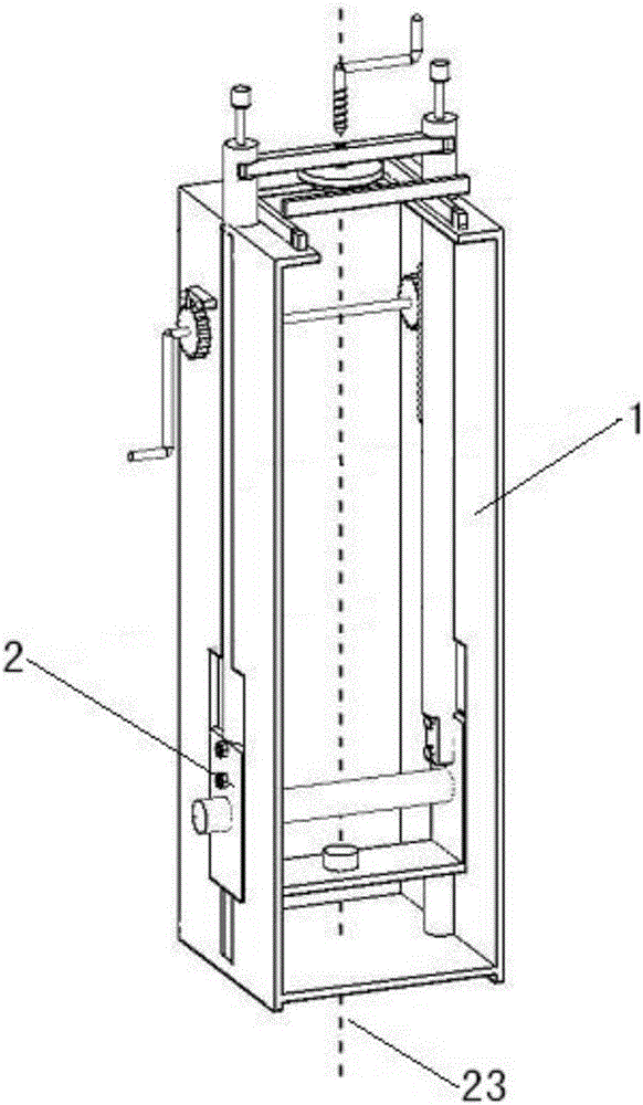
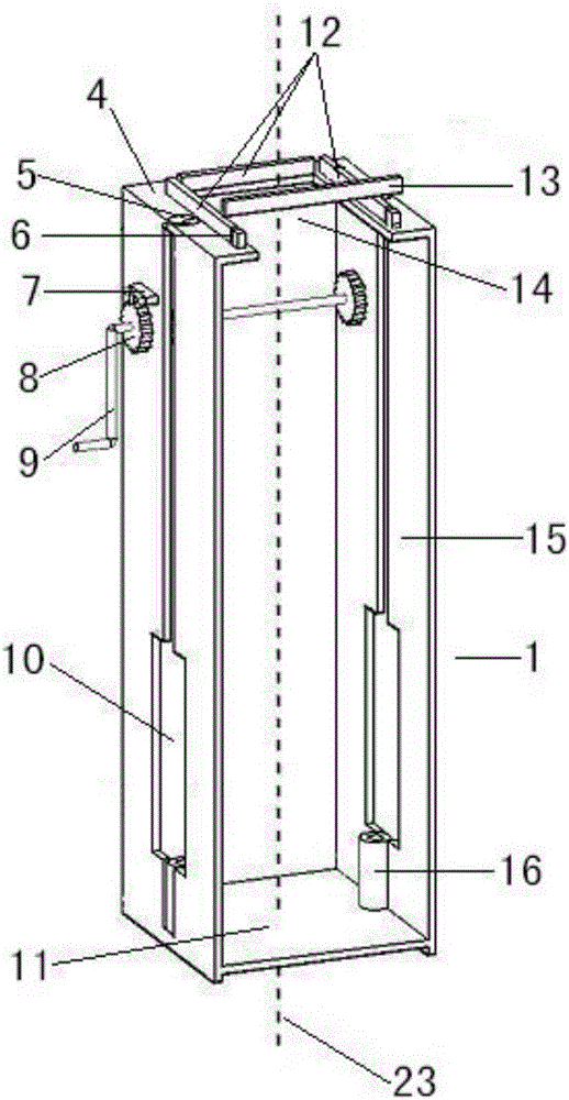
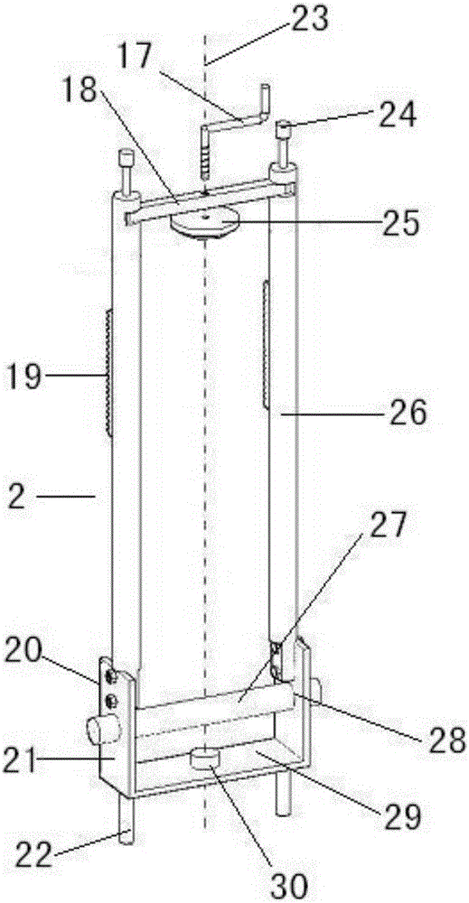
[0031] See Figure 1-Figure 6 , the installation device of the steel shell of the quick-change submerged nozzle is composed of two parts, the support frame 1 and the positioning frame 2. The positioning frame 2 is assembled in the support frame 1, and is used to fix the quick-change submerged nozzle 3, so that the quick-change submerged nozzle The vertical axis 36 of the steel channel of the nozzle 3 is perpendicular to the bottom plane of the steel shell, so that the horizontal line 40 in the center of the outlet hole 35 of the quick-change submerged nozzle is parallel to the two opposite sides of the steel shell 34, and the positioning frame 2 can carry the quick-change immersion Type nozzle 3 vertically moves up and down relative to support fr...


PUM


Abstract

The invention relates to a quick-changing submerged nozzle and steel shell installation device and method. The installation device is composed of a supporting frame and a positioning frame, wherein the positioning frame is assembled in the supporting frame and is used for fixing a quick-changing submerged nozzle to ensure that the vertical axis of a cast steel passageway of the quick-changing submerged nozzle is vertical to the bottom plane of a steel shell and the central horizontal connection line of a discharge hole of the quick-changing submerged nozzle is in parallel to two opposite sides of the steel shell, and the positioning frame can carry the quick-changing submerged nozzle to move vertically up and down relative to the supporting frame. The installation device has the advantages that the steel shell is installed before milling and grinding of a quick-changing surface, then glazing operation is performed after fire clay is dried, milling and grinding of the quick-changing surface are finally performed with the bottom surface of the steel shell as a datum, and thus the perpendicularity of the processed quick-changing surface and the cast steel passageway of the submerged nozzle is guaranteed; as the surface milling is performed in the final procedure, the processed quick-changing surface can be prevented from contamination and damages of other operation steps.

Description

technical field [0001] The invention relates to a production process equipment of a quick-change submerged nozzle, in particular to a quick-change submerged nozzle steel shell installation device and method for continuous casting. Background technique [0002] Quick-change submerged nozzle is the most widely used protective cast refractory product in the steel continuous casting production process. It is used in conjunction with a specially designed quick-change mechanism to quickly replace the submerged nozzle that has reached the end of its service life on-line to improve production efficiency. During quick change, the new submerged nozzle slides from the spare position in the quick change mechanism to the casting position by hydraulic pressure in the guide groove of the quick change mechanism, and squeezes the submerged nozzle to be replaced away from the casting position. Complete the quick replacement of the submerged nozzle under the circumstances. After the quick cha...

Claims


Application Information

Patent Timeline
IPC IPC(8): B22D41/56
CPCB22D41/56
Inventor 李波陈永范李轼保高玉明刘绍杰胡晓光徐占魁王仁贵李涛
Owner UNIV OF SCI & TECH LIAONING
Learn More