Clamp special for square part end face groove milling

A special fixture and face milling technology, which is applied in the direction of metal processing machinery parts, clamping, manufacturing tools, etc., can solve the problems of low production efficiency and long tool setting time, and achieve high production efficiency, short processing cycle, and reduce tool setting the effect of time

Inactive Publication Date: 2016-06-15
HARBIN JIANCHENG GRP
View PDF6 Cites 1 Cited by
  • Summary
  • Abstract
  • Description
  • Claims
  • Application Information

AI Technical Summary

Problems solved by technology

[0003] The purpose of the present invention is to solve the problem that there is no special fixture when milling symmetrical slots on both ends of square parts, the tool setting time is long, and the production efficiency is low, so as to provide a special fixture for milling grooves on the end faces of square parts

Method used


Image

  • Clamp special for square part end face groove milling
  • Clamp special for square part end face groove milling
  • Clamp special for square part end face groove milling

Examples


specific Embodiment approach 1

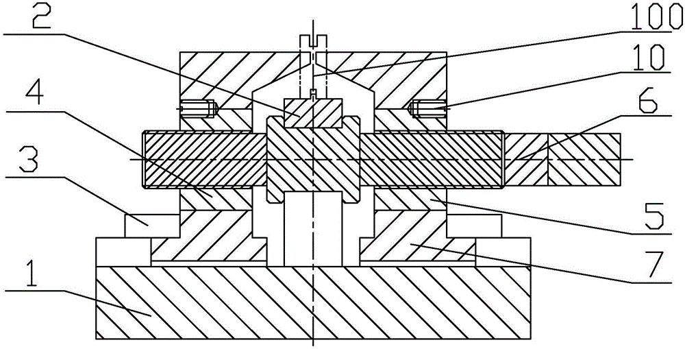
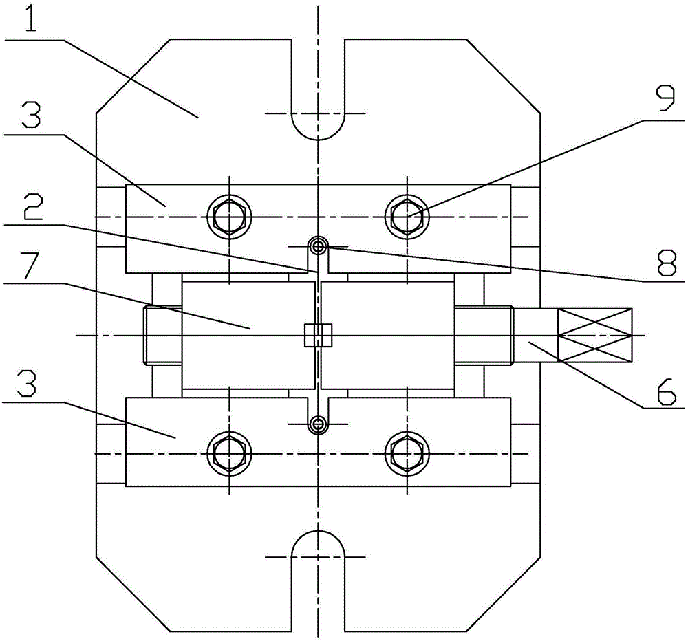
[0034] Specific implementation mode one: combine Figure 1 to Figure 19 Describe this embodiment, a special fixture for milling grooves on the end face of square parts in this embodiment, including a fixture base plate 1, a positioning block 2, a pressure plate 3, a first bushing 4, a second bushing 5, a screw rod 6 and a For clamping block 7,

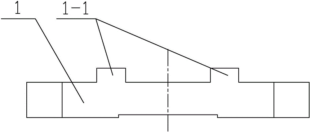
[0035] Two first bosses 1-1 parallel to each other are processed on the upper end surface of the fixture bottom plate 1,

[0036] The positioning block 2 includes a positioning base plate 2-1 and a positioning platform 2-2. The positioning platform 2-2 is fixed to the fixture base plate 1 through the positioning base plate 2-1 and screws 8. The positioning block 2 is provided with an inverted U-shaped groove 2- 4. The upper end surface of the positioning table 2-2 is processed with a second boss 2-5,

[0037] A pair of clamping blocks 7 are arranged symmetrically along the positioning block 2 and the two clamping blocks are in a door...

specific Embodiment approach 2

[0043] Specific implementation mode two: combination Figure 2 ~ Figure 4 , Figure 8 To describe this embodiment, the width L of the base 7-1 is smaller than the distance between the two first bosses 1-1, and the height of the base 7-1 is smaller than the height of the first bosses 1-1. Such a design ensures the linear movement of the clamping block on the bottom plate 1 of the fixture. Other compositions and connections are the same as those in the first embodiment.

specific Embodiment approach 3

[0044] Specific implementation mode three: combination figure 1 , Figure 5 , Figure 6 and Figure 16 To illustrate this embodiment, the inverted U-shaped groove 2-4 on the positioning block 2 is in clearance fit with the positioning section 6-2 on the screw rod 6 . Designed in this way, the screw rod 6 can be positioned. Other compositions and connections are the same as those in Embodiment 1 or Embodiment 2.


PUM


Abstract

The invention discloses a clamp special for square part end face groove milling and relates to a clamp.The problem that no clamp special for milling symmetrical grooves in the two end faces of an existing square part exists, the time for tool setting is long and the production efficiency is low is solved.The clamp special for square part end face groove milling comprises a clamp base plate, a positioning block, a press plate, a first lining, a second lining, a screw and a pair of clamping blocks, wherein two mutually parallel first bosses are machined on the upper end face of the clamp base plate, the positioning block comprises a positioning base plate and a positioning table, the positioning table is fixedly connected with the clamp base plate through the positioning base plate and a screw, a pair of clamping blocks is symmetrically arranged along the positioning block, the two clamping blocks are of portal structures, each clamping block comprises a base and a fixing block, a through hole is machined in the middle of the fixing block, a second through groove is machined in the inner side face of the fixing block, the central axes of the two through holes are located on the same straight line, the two second through grooves are formed oppositely, and each base is located between the two first bosses.The clamp special for square part end face groove milling is used for clamping square parts.

Description

technical field [0001] The invention relates to a clamp, in particular to a slot milling clamp for a square part. Background technique [0002] There is a groove at one end of the square part, and a symmetrical groove needs to be milled on the other end. However, there is no special fixture in the prior art. It is usually clamped with a vise, and one piece is clamped at a time. Due to the inconsistent size of the workpiece, The position accuracy of the processed groove is high, and the symmetry of the two grooves is 0.03, so each workpiece needs to be tool-set and the center line of the workpiece is found to ensure the accuracy of the processed groove. To ensure product quality in this way, time-consuming and labor-intensive, resulting in low production efficiency, can not meet the requirements of mass production. Contents of the invention [0003] The purpose of the present invention is to solve the problems of lack of special fixtures, long tool setting time and low pro...

Claims


Application Information

Patent Timeline
Patent Type & Authority Applications(China)
IPC IPC(8): B23Q3/06
CPCB23Q3/062
Inventor 曾庆富郭男楠孙丽丽王崇蕊宋丽平
Owner HARBIN JIANCHENG GRP
Why Eureka
Try Eureka