t-joint

A technology of rod handle and assembly, which is applied in the direction of wrench, wrench, screwdriver, etc., can solve the problems of being unable to bear on the pivot lug 112 to disperse stress, breakage, etc., to achieve enhanced safety and durability, ensure fastness, and avoid The effect of component slippage

Active Publication Date: 2017-11-24
蔡 人举
View PDF5 Cites 0 Cited by
  • Summary
  • Abstract
  • Description
  • Claims
  • Application Information

AI Technical Summary

Problems solved by technology

[0006] refer to image 3 and Figure 4 , in order to make the handle 13 fit into the shaft seat 11 without interfering with the pivot lug 112 when rotating, the distance between the pivot lug 112 must exceed the outer diameter of the C-shaped buckle 15, However, this also causes a gap g between the handle 13 and the pivot ear 112, the handle 13 cannot bear against the pivot ear 112 to disperse the stress when rotating, and it is easy to break when it is used. , the T-joint 1 still has room for improvement

Method used


Image

  • t-joint
  • t-joint
  • t-joint

Examples


Embodiment Construction

[0048] Before the present invention is described in detail, it should be noted that in the following description, similar components are denoted by the same numerals.

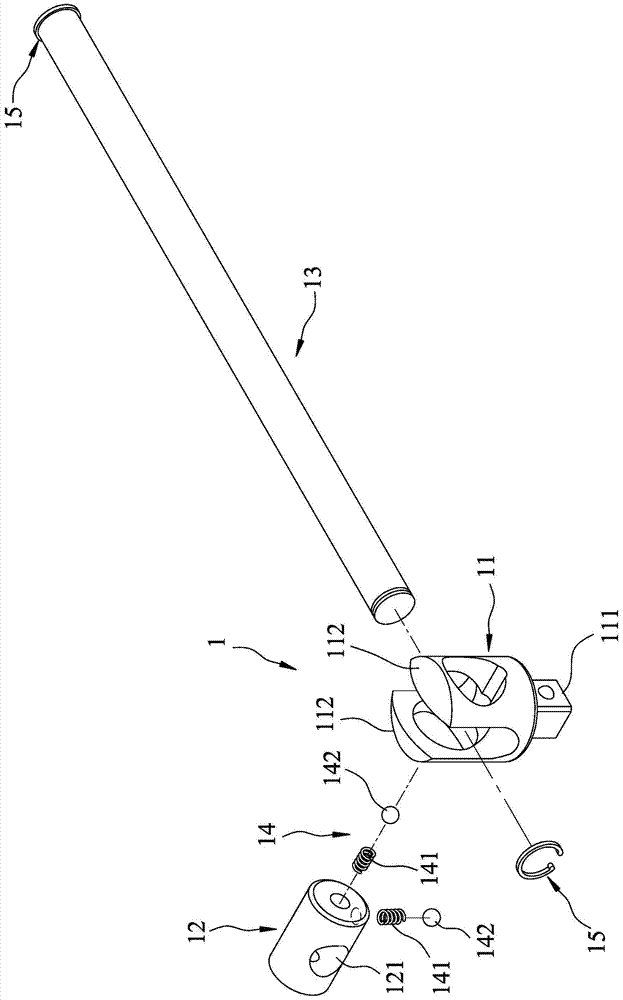
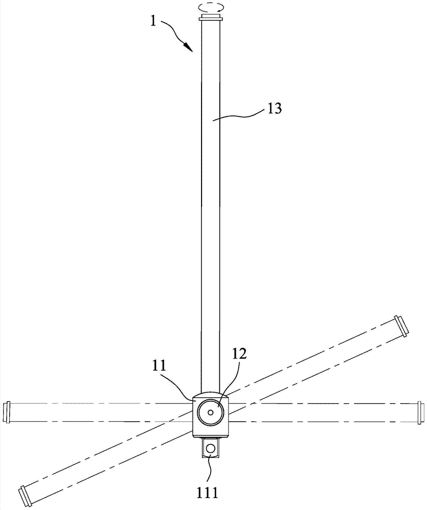
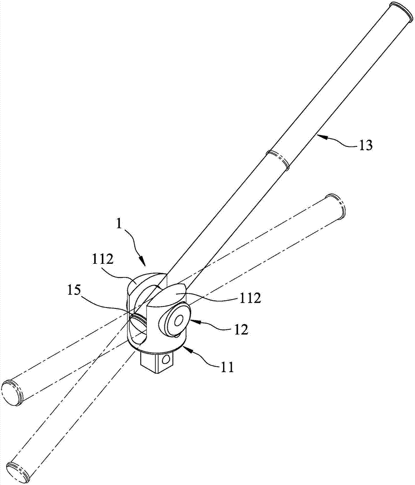
[0049] refer to Figure 5 and Figure 6 , The first embodiment of the T-shaped connecting rod of the present invention includes a shaft seat 2 , a connecting shaft 3 , a special-shaped handle 4 , and a clamping unit 5 .

[0050] The shaft seat 2 includes a body 21, two pivot lugs 22 extending outwardly from the body 21 at intervals from each other, and a pivot lug 22 extending outwardly from the body 21 opposite to the pivot lug 22 and capable of connecting with the pivot lug 22. The driving end 23 matched with different sleeves (not shown). The pivot ears 22 are respectively provided with a circular pivot hole 221 .

[0051] The assembly shaft 3 is generally cylindrical, can rotate around its own axis, pass through the pivot hole 221 and is positioned on the pivot ear 22, and includes an outer surface 31 su...


PUM


Abstract

A T-shaped connecting rod, comprising a shaft seat including two pivot lugs, a joint shaft passing through the pivot ears, and a special-shaped handle passing through the joint shaft in an interlaced manner with the joint shaft , and a clamping unit. The assembly shaft includes an outer surface, an inner surface that penetrates the outer surface radially and surrounds and defines a special-shaped through hole for the special-shaped shank to pass through, a first sinking groove that is depressed on the inner surface, and a The second sinker is recessed on the outer surface and corresponds to one of the pivot lugs. The special-shaped shaft includes two opposite locking ends each having a ring groove. The fastening unit includes two compression springs respectively arranged in the first and second sinking grooves, and two ends respectively sleeved in the compression springs, and thereby respectively resisting the outer surface of the special-shaped handle and the The top cover of the corresponding pivot ear. The T-shaped connecting rod can vertically rotate the special-shaped rod handle to drive the driving end to rotate, and the required rotating space is extremely small, which is suitable for narrow working spaces.

Description

technical field [0001] The invention relates to a T-shaped connecting rod, in particular to a T-shaped connecting rod which can be used in a narrow environment and can ensure the tightness of assembly of its own components. Background technique [0002] refer to figure 1 and figure 2 , an existing T-shaped connecting rod 1, as disclosed in China Taiwan Invention Patent Publication No. I321081, includes a shaft seat 11 with a driving end 111 and two pivot ears 112, and a shaft seat 11 that is rotatably worn on the pivot. Described pivot ear 112 and has the assembly shaft 12 of a radial through hole 121, a bar handle 13 that passes through this through hole 121 and interlaced with this assembly shaft 12, and utilizes two compression springs 141 to match two The fastening force resisted by the steel ball 142 links the components and prevents the fastening unit 14 from autonomous displacement of the components. In this way, the handle 13 can slide axially relative to the ass...

Claims


Application Information

Patent Timeline
Patent Type & Authority Patents(China)
IPC IPC(8): B25B27/14B25B13/06B25B23/00
CPCB25B13/06B25B23/00B25B27/14B25G1/066B25B23/0028B25B23/16B25G1/063
Inventor 蔡人举
Owner 蔡 人举
Why Eureka
Try Eureka