Supercharge Your Innovation With Domain-Expert AI Agents!

Method for forming cut line and device for forming cut line

A cutting line and circular technology, which is applied in the field of cutting line forming method and forming device, can solve problems such as difficulty in stably achieving high lamination accuracy, and achieve the effects of reducing lamination failure, improving lamination accuracy, and improving precision

Active Publication Date: 2016-06-15
NITTO DENKO CORP
View PDF4 Cites 1 Cited by
  • Summary
  • Abstract
  • Description
  • Claims
  • Application Information

AI Technical Summary

Problems solved by technology

However, if a plurality of optical films having different shapes are continuously bonded to the panel member, it is particularly difficult to stably realize the high bonding accuracy required for recent optical display devices.

Method used


Image

  • Method for forming cut line and device for forming cut line
  • Method for forming cut line and device for forming cut line
  • Method for forming cut line and device for forming cut line

Examples


no. 1 approach

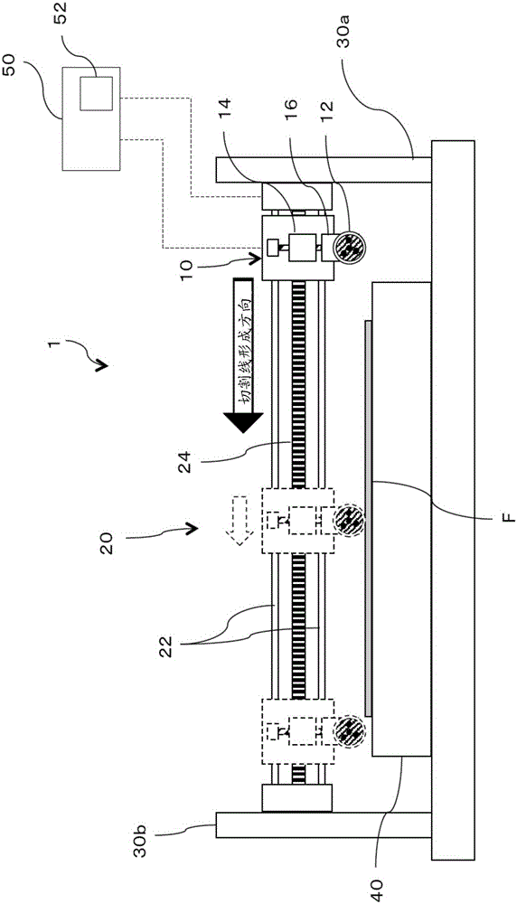
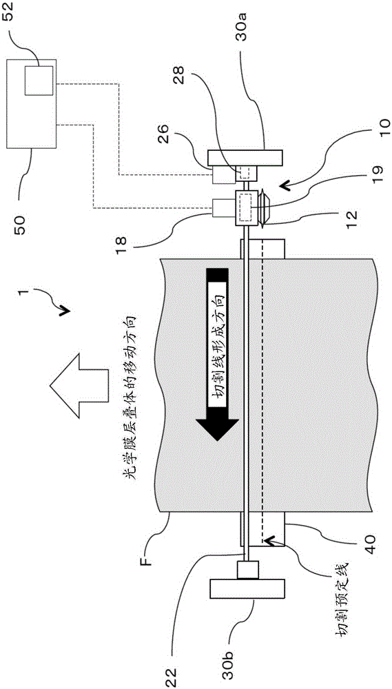
[0072] figure 2 It is a schematic side view showing the configuration of the dicing line forming apparatus 1 according to the first embodiment of the present invention, image 3 It is a schematic plan view showing the structure of the dicing line forming apparatus 1 . In this embodiment, the rotational speed of the circular cutter 12 is read by a detection unit such as an encoder, and the circular cutter 12 is set to a reference state based on the read result. The dicing line forming apparatus 1 includes the dicing unit 10 that cuts the optical film laminate F, and the dicing unit moving mechanism 20 that reciprocates the dicing unit 10 in the width direction of the optical film laminate F (cut line forming direction). The dicing line forming apparatus 1 further includes a dicing table 40 on which the optical film laminate F is placed.

[0073] The cutting unit 10 includes a circular blade 12 , a height adjustment unit 14 that adjusts the position of the circular blade 12 w...

no. 2 approach

[0096] Next, a dicing line forming apparatus 1' according to a second embodiment of the present invention will be described. Figure 7 It is a schematic plan view showing the configuration of the dicing line forming apparatus 1' according to the second embodiment of the present invention, Figure 8 A dicing line forming method 300 according to the second embodiment is shown. In this embodiment, for example, a reading unit using a camera or the like can read a mark or the like on the side surface of the circular cutter 12, and based on the read result, the circular cutter 12 can be set as Baseline status.

[0097] The basic structure of the cutting line forming apparatus 1' is the same as that of the cutting line forming apparatus 1 of the first embodiment, except that the cutting line forming apparatus 1' is provided with a reading part 32 and an illumination 34, and the reading part 32 and the illumination 34 can read the mark M marked on the side surface of the circular cu...


PUM


Abstract

Provided are a device and a method for forming a cut line which are able to start cutting by constantly bringing the same position of a round cutter into contact with a side end part of an optical film laminate when forming each of a plurality of cut lines. This method includes: a step for rotating the round cutter; a step for bringing a predetermined position on the external periphery of the round cutter into contact with a side end part of an optical film laminate and starting the cutting of the optical film laminate; a step for forming cut lines on the optical film laminate while moving the round cutter in the width direction of the optical film laminate; and a step for conveying the optical film laminate by a distance previously set as the distance between one cut line and the next cut line.

Description

technical field [0001] The present invention relates to a method and apparatus for forming a cut line on an optical film laminate, and more particularly, to a method and apparatus for forming a cut line that can be controlled to In each of the plurality of cutting lines, the depths of the cutting lines are made to be the same depths at positions where the lateral distance from the side end of the optical film laminate is the same. Background technique [0002] In recent years, optical display apparatuses, such as a liquid crystal display apparatus and an organic electroluminescent display apparatus by which an optical film was bonded to a glass substrate, have become popular as displays, such as a television receiver. In the manufacture of optical display devices, the independent bonding method has been conventionally used, that is, a plurality of optical film sheets cut out from the tape-shaped optical film in advance in a process other than the manufacturing process of the...

Claims


Application Information

Patent Timeline
Patent Type & Authority Applications(China)
IPC IPC(8): B26D1/15B26D7/26B26D5/00
CPCB26D1/18B26D3/00
Inventor 三岛隼前田实由良友和小塩智
Owner NITTO DENKO CORP
Features
  • R&D
  • Intellectual Property
  • Life Sciences
  • Materials
  • Tech Scout
  • Unparalleled Data Quality
  • Higher Quality Content
  • 60% Fewer Hallucinations
Learn More