Wheel sensor calibration system and control method thereof

A wheel sensor and calibration system technology, which is applied in the field of wheel sensor calibration system and its control, can solve the problems of non-displacement installation, errors and misactivation in operation links, etc., and achieves the effect of avoiding misactivation.

Active Publication Date: 2016-06-15
HEFEI SOFTEC AUTO ELECTRONICS
View PDF7 Cites 6 Cited by
  • Summary
  • Abstract
  • Description
  • Claims
  • Application Information

AI Technical Summary

Problems solved by technology

When using the existing trigger calibration method to calibrate one of the tires, due to the transmission characteristics of LF low-frequency radio waves spreading around, it is easy to be received by sensors other than the target tire and be falsely activated.
The existing technology is to first trigger the calibration of the trigger, paste the calibrated wheel position code on the trigger, and then install the sensors on the corresponding axles and wheel positions one by one according to the wheel position code. Do not install them in a wrong position, otherwise they will not be able to play. Security warning function of TPMS
However, since the above-mentioned calibration, tire loading and truck loading are not on the same site, errors are prone to occur in the operation process, which cannot meet the requirements of the assembly line of truck companies

Method used


Image

  • Wheel sensor calibration system and control method thereof
  • Wheel sensor calibration system and control method thereof
  • Wheel sensor calibration system and control method thereof

Examples


Embodiment Construction

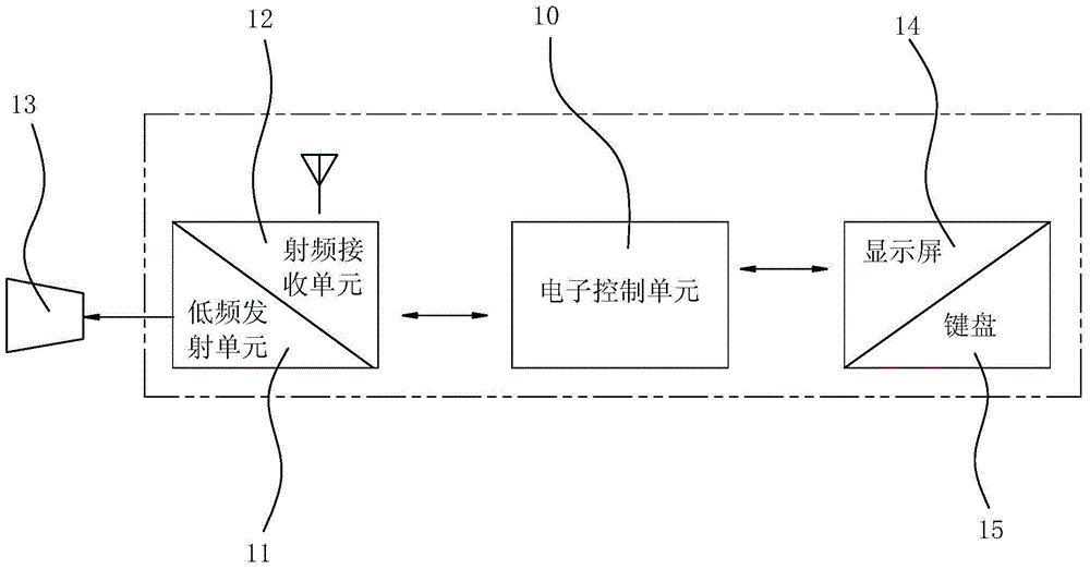
[0016] Such as figure 1 As shown, a wheel sensor calibration system includes an electronic control unit 10, a low-frequency signal transmitting unit 11, and a radio-frequency signal receiving unit 12. The electronic control unit 10 generates a trigger signal, which is transmitted by the low-frequency signal transmitting unit 11 through a directional The antenna 13 wirelessly sends to the target wheel sensor, and the target wheel sensor will send a response signal containing the sensor ID identification code after receiving the trigger signal, and the radio frequency signal receiving unit 12 receives the response signal and transmits the response signal to the electronic control Unit 10.

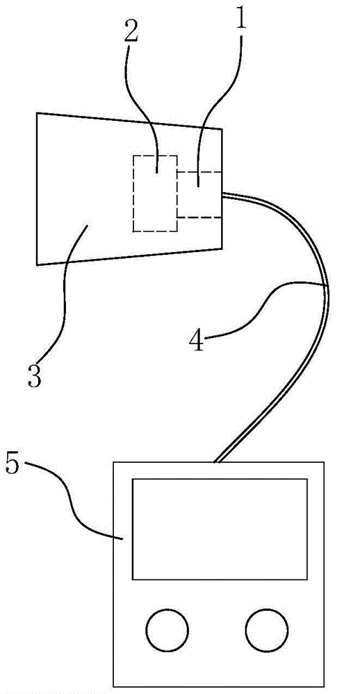
[0017] Such as figure 2 As shown, the directional transmission antenna 13 includes an excitation unit 1, an antenna oscillator 2 and a cluster cover 3, and the excitation unit 1 and the antenna oscillator 2 are installed in the cluster cover 3, and the cluster cover 3 is made of high magnet...


PUM


Abstract

The invention belongs to the field of automobile assembling and particularly relates to a wheel sensor calibration system and a control method thereof. A directional transmission antenna is adopted for directionally sending a low-frequency trigger signal to a target wheel sensor, and wheel sensors nearby are prevented from being mistakenly activated. In addition, feedback type power gradual change triggering is adopted, and the power of the trigger signal is gradually increased from the preset lowest power till the target wheel sensor sends a response signal. It is guaranteed that the trigger signal activates the target wheel sensor through the minimum receivable power. The wheel sensors nearby are further prevented from being mistakenly activated.

Description

technical field [0001] The invention belongs to the field of automobile assembly, and in particular relates to a wheel sensor calibration system and a control method thereof. Background technique [0002] Tire Pressure Monitoring System (TPMS) has been widely used in passenger vehicles such as cars and vans. Since the technical bottleneck of multi-tire trigger calibration of trucks has not been solved for a long time, it has restricted the application of TPMS systems in commercial vehicles, especially trucks. Development of enterprise security assistance system configuration. The load of the truck relies on multiple axles and multiple tires to share the load weight, and two wheels are installed side by side at both ends of the axle. If the compartment is two axles, four wheels are installed at the same end of the two axles and are very close to each other, which means that the sensors in the four tires may sometimes be very close to each other. When using the existing trig...

Claims


Application Information

Patent Timeline
Patent Type & Authority Applications(China)
IPC IPC(8): B60C23/04
CPCB60C23/0474B60C23/0481
Inventor 许永华戚利民刘坤梅炜炜顾留刚黄军
Owner HEFEI SOFTEC AUTO ELECTRONICS
Why Eureka
Try Eureka