Two-way V-shaped thrust lever upper bracket and bracket beam assembly

A technology of thrust rods and frame beams, applied in the field of thrust rod brackets, can solve the problems of increasing the cost of manufacturing, processing and management, and the large number of parts and components, and achieve the effects of strong position accuracy, high assembly efficiency and high precision

Active Publication Date: 2016-06-15
DONGFENG COMML VEHICLE CO LTD
View PDF6 Cites 8 Cited by
  • Summary
  • Abstract
  • Description
  • Claims
  • Application Information

AI Technical Summary

Problems solved by technology

Although this design can enhance the connection stability and improve the service life of the V-push bracket, it still has the following defects: this design can only be responsible for the installation of the V-shaped thrust rod in one direction of the middle axle or rear axle, and the number of parts is relatively large , which increases the cost of manufacturing, processing and management

Method used


Image

  • Two-way V-shaped thrust lever upper bracket and bracket beam assembly
  • Two-way V-shaped thrust lever upper bracket and bracket beam assembly
  • Two-way V-shaped thrust lever upper bracket and bracket beam assembly

Examples


Embodiment 1

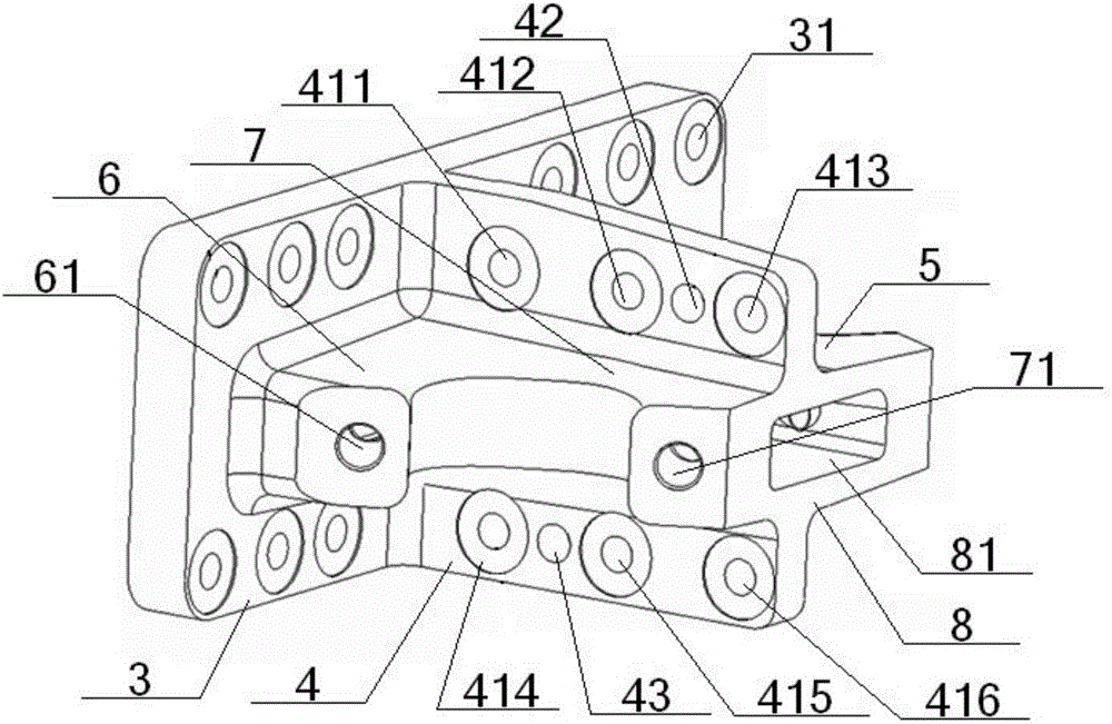
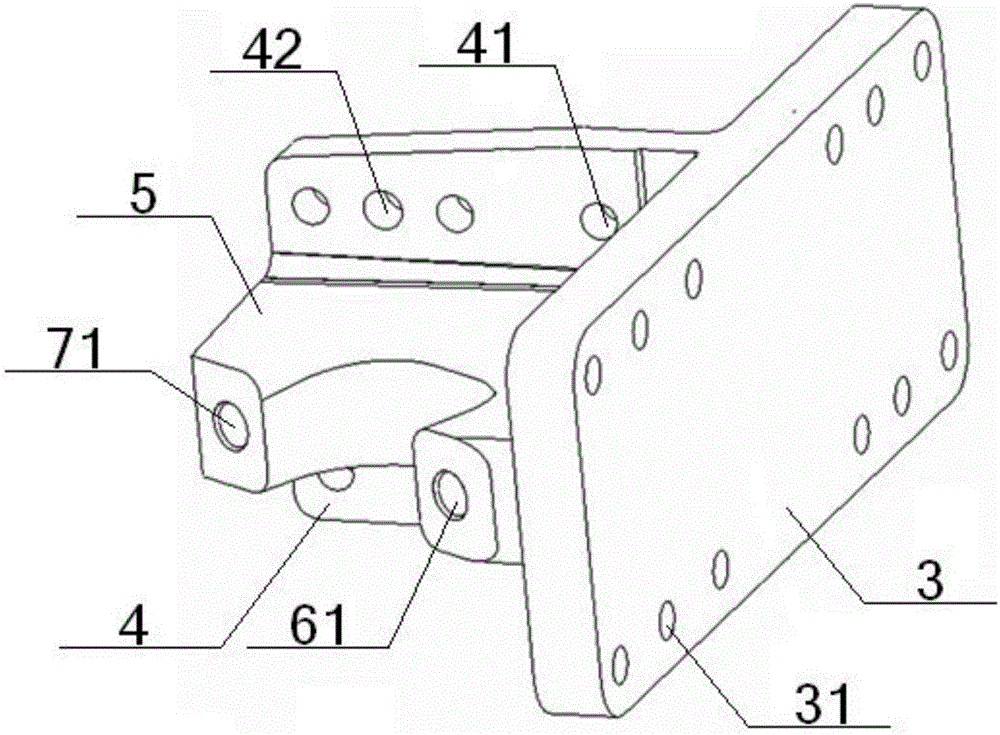
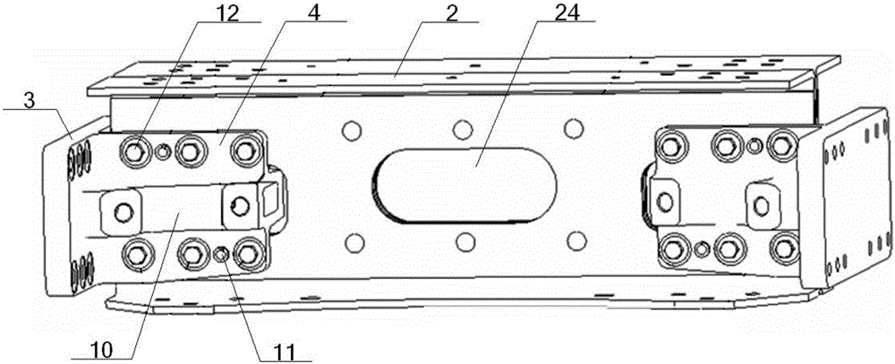
[0054] see Figure 1 to Figure 6 , a two-way V-shaped thrust rod upper bracket, comprising a longitudinal beam connecting plate 3, a cross beam connecting plate 4 and a support seat 5, the longitudinal beam connecting plate 3 is fixedly connected to the vehicle frame longitudinal beam 1, and the cross beam connecting plate 4 is connected to the vehicle The frame crossbeam 2 is fixedly connected, the number of the support base 5 is two, the middle part of the longitudinal beam connecting plate 3 is vertically connected with the bottom of the crossbeam connecting plate 4, and the positive and negative sides of the middle part of the crossbeam connecting plate 4 are connected with the A supporting seat 5 is respectively arranged between the longitudinal beam connecting plates 3, and the two supporting seats 5 are plane-symmetrical with respect to the beam connecting plate 4, and longitudinal beam connecting plates 3 and supporting seats 5 are arranged on both sides of the upper an...

Embodiment 2

[0056] Basic content is the same as embodiment 1, the difference is:

[0057] The support seat 5 is an L-shaped structure, including a short vertical part 6 and a long horizontal part 7 connected to each other, the bottom of the short vertical part 6 is connected to the middle part of the longitudinal beam connecting plate 3, and the bottom of the long horizontal part 7 is connected to the cross beam. The middle part of the connecting plate 4 is bonded and connected, the outer end of the short vertical part 6 is provided with a longitudinal connecting rod hole 61, the inner end of the short vertical part 6 is connected with the inner end of the long horizontal part 7, and the outer end of the long horizontal part 7 is opened There is a transverse link hole 71 , and the projection of the transverse link hole 71 on the longitudinal beam connecting plate 3 is located between the projection of the longitudinal link hole 61 on the longitudinal beam connecting plate 3 and the bottom ...

Embodiment 3

[0059] Basic content is the same as embodiment 1, the difference is:

[0060] An upper pin hole 42 and a lower pin hole 43 are respectively arranged on the upper and lower sides of the cross-beam connection plate 4 and the supporting seat 5, and the center connection between the upper pin hole 42 and the lower pin hole 43 The line is an oblique line; the positional relationship between the upper pin hole 42 and the lower pin hole 43 is: the upper pin hole 42 is set near the top of the beam connecting plate 4, and the lower pin hole 43 is set near the bottom of the beam connecting plate 4, or the upper pin hole 42 are arranged near the bottom of the crossbeam connecting plate 4, and the lower pin holes 43 are arranged near the top of the crossbeam connecting plate 4. The upper pin holes 42 , lower pin holes 43 and their corresponding positioning pins 11 are interference fit, and the longitudinal beam bolt holes 31 , cross beam bolt holes 41 and their corresponding connecting bo...


PUM


Abstract

The invention relates to a two-way V-shaped thrust lever upper bracket. The two-way V-shaped thrust lever upper bracket comprises a longitudinal beam connecting plate, a cross beam connecting plate and two support seats, wherein the middle of the longitudinal beam connecting plate is vertically connected to the bottom of the cross beam connecting plate, the two support seats are respectively arranged between the positive and negative side surfaces of the middle of the cross beam connecting plate and the longitudinal beam connecting plate, the two support seats are in plane symmetry according to the cross beam connecting plate, longitudinal beam bolt holes are formed in the upper and lower sides of the connecting positions of the longitudinal beam connecting plate and the support seats, and cross beam bolt holes and pin holes are formed in the upper and lower sides of the connecting positions of the cross beam connecting plate and the support seats. The upper bracket is combined with U-shaped grooves formed in both ends of a frame cross beam, so as to form a bracket beam assembly. By adopting the design, a thrust lever can be installed in two directions, the quantity of components and parts is reduced, the precision of the installation position is higher, the installation and removal are convenient, the assembly efficiency is higher, and the maintenance convenience is good.

Description

technical field [0001] The invention relates to a thrust rod bracket fixed on the vehicle frame, in particular to a bidirectional V-shaped thrust rod upper bracket and bracket crossbeam assembly, which is particularly suitable for the thrust rod of the rear axle in bidirectional installation and reduces the number of parts . Background technique [0002] Thrust rods are mainly used on single-axle or double-rear-axle heavy-duty vehicles with non-independent suspension of trucks or passenger cars. Bridge shifted. Thrust rods are mainly divided into straight thrust rods and V-shaped thrust rods. Generally, straight thrust rods can only prevent the front and rear displacement of the axle, while V-shaped thrust rods can not only prevent the front and rear displacement of the axle, but also prevent the left and right displacement of the axle. , so as to avoid the movement interference between the leaf spring and the tire due to the large left and right displacement of the axle w...

Claims


Application Information

Patent Timeline
Patent Type & Authority Applications(China)
IPC IPC(8): B60G7/00B62D21/02
CPCB60G7/00B62D21/02
Inventor 周生权杨良明范培斌潘学玉彭显威李应涛易建武王江伟龚龙
Owner DONGFENG COMML VEHICLE CO LTD
Why Eureka
Try Eureka