
Multi-position undercarriage

A multi-position, landing gear technology, applied in the field of aircraft, can solve problems such as impossible to obtain

Active Publication Date: 2016-06-15
THE BOEING CO
View PDF7 Cites 6 Cited by
  • Summary
  • Abstract
  • Description
  • Claims
  • Application Information

AI Technical Summary

Problems solved by technology

although traditionally such equipment is available in a maintenance hangar or other support facility, it is not possible to obtain it when the aircraft is deployed in the field

Method used


Image

  • Multi-position undercarriage
  • Multi-position undercarriage
  • Multi-position undercarriage

Examples


Embodiment Construction

[0022] The following detailed description refers to the accompanying drawings, which illustrate specific embodiments of the disclosure. Other embodiments having different structures and operations do not depart from the scope of the present disclosure. The same reference numerals may refer to the same elements or components in different drawings.

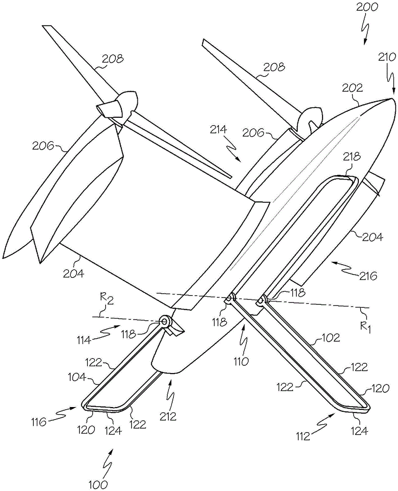
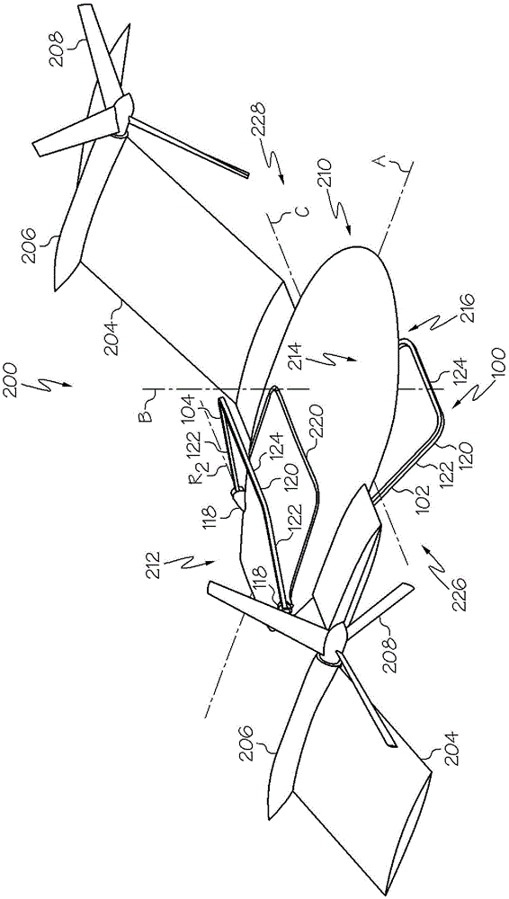
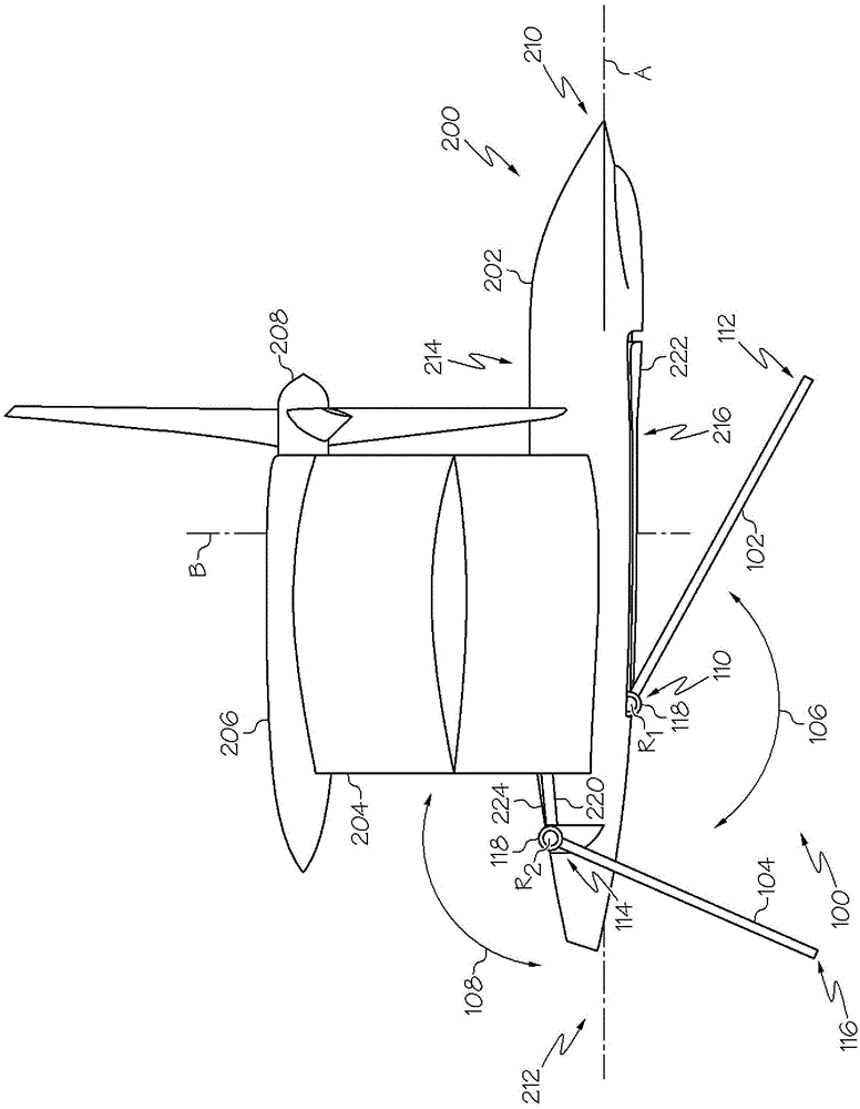
[0023] refer to Figure 1-Figure 6 and Figure 10 , which illustrates one embodiment of the disclosed multi-position landing gear, generally designated 100 , for use on an aircraft 200 . Aircraft 200 may be any type of manned or unmanned aerial vehicle including, but not limited to, fixed wing aircraft, rotary wing aircraft, and the like. As one specific, non-limiting example, aircraft 200 may be an unmanned aerial vehicle ("UAV") as illustrated. As another specific, non-limiting example, aircraft 200 may be a tail-sitter or other type of VTOL aircraft.

[0024] In an example embodiment, aircraft 200 may include a fuselage 202 ...


PUM


Abstract

The invention discloses a multi-position undercarriage for aircraft, the multi-position undercarriage may comprise a first aircraft landing skid disposed on the bottom side of the aircraft, and a second one landing skid disposed on the top side or on the bottom side of the aircraft, wherein the first landing skid and second landing skid are rotatable with respect to the aircraft.

Description

technical field [0001] The present invention relates generally to aircraft, and more particularly to multi-position landing gear for aircraft. Background technique [0002] The landing gear typically supports the aircraft when the aircraft is not in flight, allowing the aircraft to take off, land, refuel, be serviced, and taxi. Depending on the surface and whether the aircraft operates vertically (eg, vertical take-off and landing "VTOL") or is able to glide along the surface, common landing gear consists of wheels, landing skids, skids, pontoons, or a combination of these and other elements. The undercarriage can be fixed in a single position or can be retracted and deployed as desired. Faster aircraft often have retractable landing gear (eg, the aircraft's landing gear is housed into the wheel wells during flight) that folds up during flight to reduce air resistance or resistance. Conventional takeoff and landing ("CTOL") aircraft typically have wheels to facilitate roll...

Claims


Application Information

Patent Timeline
IPC IPC(8): B64C25/10B64C25/52
CPCB64C25/10B64C25/52B64U70/80B64C29/0025B64C25/66B64C25/14B64C25/36
Inventor J·H·哈里斯三世D·I·纽曼
Owner THE BOEING CO
Learn More