A structure-improved milk powder spoon

A technology of milk powder and spoon body, which is applied in packaging and other directions, can solve the problem that milk powder cannot be effectively removed, and achieve the effect of simple structure, strong practicability, and waste reduction

Active Publication Date: 2018-08-28
王炯铭
View PDF6 Cites 0 Cited by
  • Summary
  • Abstract
  • Description
  • Claims
  • Application Information

AI Technical Summary

Problems solved by technology

[0004] The invention provides a milk powder spoon with improved structure, the main purpose of which is to overcome the defect that the existing milk powder spoon cannot effectively remove the residual milk powder at the bottom of the milk powder tank

Method used


Image

  • A structure-improved milk powder spoon
  • A structure-improved milk powder spoon
  • A structure-improved milk powder spoon

Examples


Embodiment 1

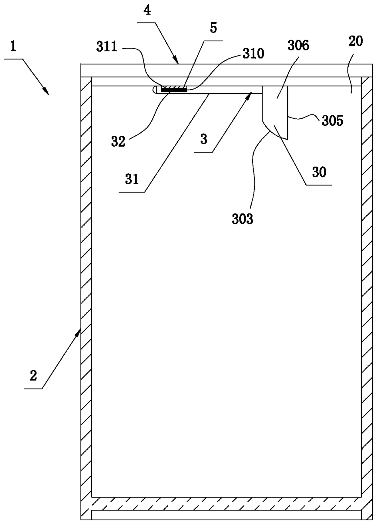
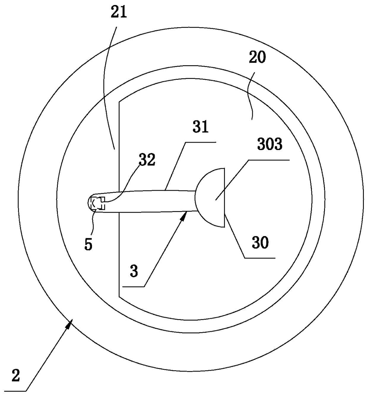
[0031] refer to figure 1 , figure 2 and image 3 . An easy-to-use milk powder can 1, comprising a can body 2, a milk powder scoop 3 and a can lid 4, the milk powder scoop 3 includes a scoop body 30 and a spoon handle 31 connected to one end of the scoop body 30, on the scoop handle 31 At least one magnet 32 ​​is provided, and at least one iron part 5 is arranged at the mouth position 20 of the can lid 4 or the tank body 2, and the milk powder scoop 3 communicates with the iron part through the magnet 32 ​​on its spoon handle 31. 5 is connected by magnetic force, and the spoon handle 31 is installed on the tank mouth position 20 of the tank cover 4 or the tank body 2 in a transverse arrangement. The present invention has simple structure and strong practicability. A magnet 32 ​​is set on the spoon handle 31 of the milk powder spoon 3, and an iron material capable of magnetically connecting with the magnet 32 ​​is set at the position of the can mouth of the can lid 4 or the ...

Embodiment 2

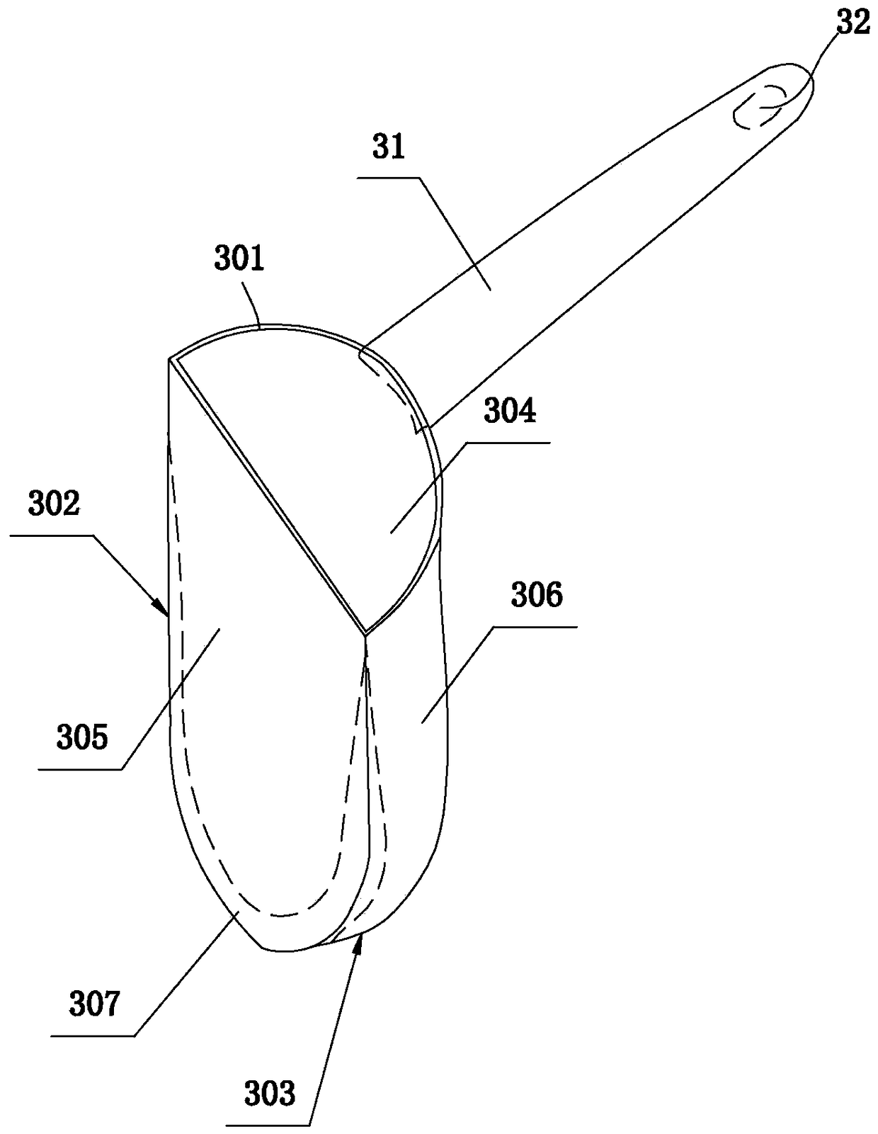
[0039] In addition, refer to image 3 and Figure 6 . In another preferred embodiment of the present invention, the spoon handle 31 includes a fixed handle 313 connected to the spoon body 30 and a flexible bending part 314 rotatably connected to the end of the fixed handle 313, so The accommodating groove 310 is disposed on the flexible bending portion 314 .

[0040] More specifically, the accommodating groove 310 is disposed in the middle of the flexible bending portion 314, and the flexible bending portion 314 is pivotally connected to the end of the fixed handle 313 on the side where the accommodating groove 310 is located. , the rotation angle between the flexible bending part and the fixed handle is 0°-90°. More preferably, the flexible bending part can form two arrangement states of engaging at an angle of 0 degree and engaging at an angle of 90 degrees with the end of the fixed handle 313 . By setting the flexible bending part 314 and configuring the magnet 32 ​​on ...


PUM


Abstract

A milk powder scoop with an improved structure comprises a major scoop body and a scoop handle which is connected with one end of the major scoop body. The major scoop body comprises a scoop mouth, a minor scoop body which is formed by the downward extension of the periphery of the scoop mouth, and a scoop bottom which is connected with the tail end of the minor scoop body. An accommodating cavity used for containing milk powder is jointly formed by the minor scoop body and the scoop bottom in a surrounded manner. The minor scoop body comprises at least a straight wall and an arc wall with two ends connected with the two ends of the straight wall correspondingly. The upper portion of the accommodating cavity is a semi-cylindrical cavity jointly formed by the straight wall and the arc wall in a surrounded manner. By means of refitting the minor scoop body of the milk powder scoop to a semi-cylindrical structure mainly formed by the straight wall and the arc wall, the straight wall of the minor scoop body is made to attach to the bottom of a milk powder tin closely. During the process of milk powder scooping, dead angle positions where the milk powder cannot be scooped can be eliminated by the straight wall to guarantee that residual milk powder at the bottom of the milk powder tin can be utilized and thus the waste of milk powder during the process of using the milk powder tin can be reduced effectively.

Description

technical field [0001] The invention relates to a milk powder scoop, in particular to a milk powder scoop with improved structure. Background technique [0002] According to data from the United States Department of Agriculture, the global annual consumption of milk powder is more than 6 million tons. Canned milk powder packaging is favored by most consumers because of its solid packaging material, good airtightness and moisture resistance, and long storage time and shelf life. Therefore, milk powder packaged in bottles and cans accounts for about two-thirds of consumption. Calculated based on the capacity of most canned milk powder of 900 ml, about 450,000 bottles of milk powder are consumed globally every year. With such a large consumer group (both of us grew up drinking milk powder), what problems have we encountered in the process of using milk powder spoons? [0003] Through the applicant's actual investigation and research, it is found that there are the following d...

Claims


Application Information

Patent Timeline
Patent Type & Authority Patents(China)
IPC IPC(8): B65D77/24
CPCB65D77/245
Inventor 王炯铭侯文颖
Owner 王炯铭
Why Eureka
Try Eureka