Material vibrating device

A material vibrating device and material technology, applied in vibrating conveyors, transportation and packaging, conveyors, etc., can solve problems such as difficulty in meeting the load-bearing requirements of heavy loads, increasing production line setup and operating costs, and complex drive device structures. Achieve the effects of improving mechanical conversion efficiency, simplifying the vibration generating structure, and smoothing the vibration process

Inactive Publication Date: 2016-06-15
何慧敏
View PDF4 Cites 0 Cited by
  • Summary
  • Abstract
  • Description
  • Claims
  • Application Information

AI Technical Summary

Problems solved by technology

However, some existing angle-adjusted vibration methods are difficult to meet the load-bearing requirements of heavy loads during the vibration process
Moreover, the drive device is often complex in structure and occupies a large area or space, which brings additional requirements for the installation of the processing line and the use of the factory building, and increases the production line setup and operating costs

Method used


Image

  • Material vibrating device
  • Material vibrating device
  • Material vibrating device

Examples


Embodiment Construction

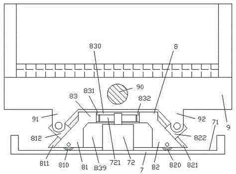
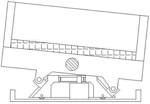
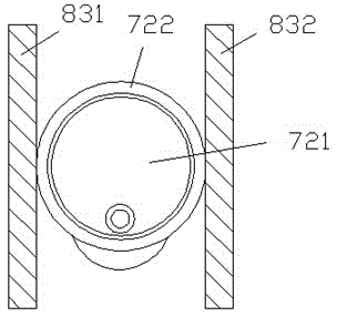
[0010] Combine below Figure 1-4 The present invention will be described in detail.

[0011] A material vibrating device according to an embodiment, comprising a frame 7, a vibrating material containing part 9 hinged to the upper part of the frame 7 through a hinge shaft 90, and The vibration-driven slider 8 that moves left and right on the roller walking track 71, wherein the vibration-driven slider 8 includes a middle main body portion 83 and two inclined portions 81, 82 symmetrically arranged left and right, the two inclined portions 81, 82 are respectively provided with mutually symmetrical slope chute 811, 821, in order to respectively carry the left support slider 812 and the right support slider 822 to slide, and the left support slider 812 and the right support slider 822 are arranged symmetrically on the The support protrusions 91, 92 at the left and right ends of the lower side of the vibrating material containing part 9 are hinged; wherein, the vibration driving sl...


PUM


Abstract

A material vibrating device comprises a machine frame (7), a vibrated material containing component (9) and a vibration driving sliding block (8), wherein the vibrated material containing component (9) is hinged to the upper part of the machine frame (7) through a hinged shaft (90); the vibration driving sliding block (8) can move left and right on a roller travelling track (71) fixed at the bottom of the machine frame (7); the vibration driving sliding block (8) comprises a middle main body part (83), a left inclined surface part (81) and a right inclined surface part (82); the two inclined surface parts (81 and 82) are arranged symmetrically and are provided with inclined surface sliding grooves (811 and 821) respectively; the inclined surface sliding grooves (811 and 821) are mutually symmetric and are used for allowing a left support sliding block (812) and a right support sliding block (822) to slide in respectively; and the left support sliding block (812) and the right support sliding block (822) are respectively hinged to support bulges (91 and 92), which are symmetrically arranged at the left and right ends on the lower side of the vibrated material containing component (9).

Description

technical field [0001] The invention relates to the field of material processing, in particular to a material vibration device. Background technique [0002] In the field of material processing, it is often necessary to carry out vibratory processing on materials, such as grinding and rust removal of small parts, material granulation and rounding, material screening and other processing processes, etc., which requires a material vibration holding device capable of carrying loads. In some processing fields, it is often necessary to perform vibration processing on heavy workpieces. This often makes the material holding part need to carry a huge weight. [0003] During the vibration process, it is necessary to reciprocally adjust the angle of the material holding part to meet the requirements of the frequency and amplitude of the vibration of the material. However, some existing angle-adjusted vibration methods are difficult to meet the requirements of carrying heavy loads du...

Claims


Application Information

Patent Timeline
Patent Type & Authority Applications(China)
IPC IPC(8): B65G27/12B65G27/34
CPCB65G27/12B65G27/34
Inventor 何慧敏
Owner 何慧敏
Why Eureka
Try Eureka