Breaker mechanism maintenance trolley

A technology of circuit breaker mechanism and trolley, which is applied to portable lifting devices, hoisting devices, etc., can solve the problems of complicated and inconvenient process, low height and unadjustable, small disassembly and assembly space, etc.

Active Publication Date: 2016-06-15
STATE GRID FUJIAN ELECTRIC POWER CO LTD +2
View PDF9 Cites 6 Cited by
  • Summary
  • Abstract
  • Description
  • Claims
  • Application Information

AI Technical Summary

Problems solved by technology

[0002] During the dismantling and overhaul of the circuit breaker mechanism, it is necessary to remove and install bearings, ratchets, circlips and other accessories from different angles of the movement. In particular, some accessories have small disassembly space and limited angles, requiring multiple people to rotate the heavy movement to the required installation angle without shaking, and then one person disassembles and assembles the accessories. Since the movement is directly placed on the ground or a small platform, the height is low and cannot be adjusted. At the same time, after the mechanism is assembled, it needs to be hoisted several times. Movement; the inspection and maintenance of the circuit breaker mechanism requires the cooperation of multiple people, which is extremely labor-intensive, and even the work cannot be completed when the personnel are tense; At the same time, it may cause deformation or damage to the movement; when the person who installs the accessories needs a certain angle to install and debug, he must constantly instruct others to rotate the angle, which is complicated and inconvenient; the movement is placed directly on the ground or on a small platform , the height is low and cannot be adjusted, and the operators need to bend their bodies frequently to work, which makes the staff fatigue inefficient; after the mechanism is assembled, the mechanism needs to be moved to the circuit breaker assembly area, and the heavier mechanism needs to be hoisted to complete the movement. Potential safety hazards, and processes such as binding slings are time-consuming and laborious

Method used


Image

  • Breaker mechanism maintenance trolley
  • Breaker mechanism maintenance trolley
  • Breaker mechanism maintenance trolley

Examples


Embodiment Construction

[0020] In order to make the above-mentioned features and advantages of the present invention more comprehensible, the following specific embodiments are described in detail with reference to the accompanying drawings.

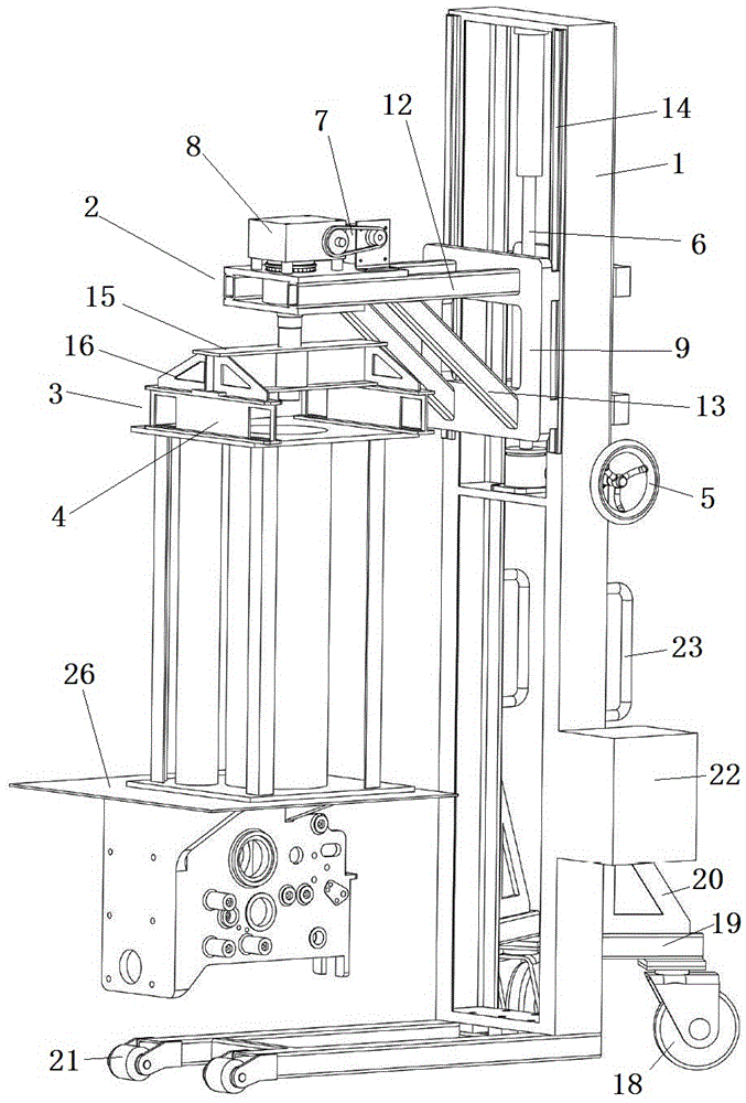
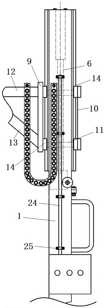
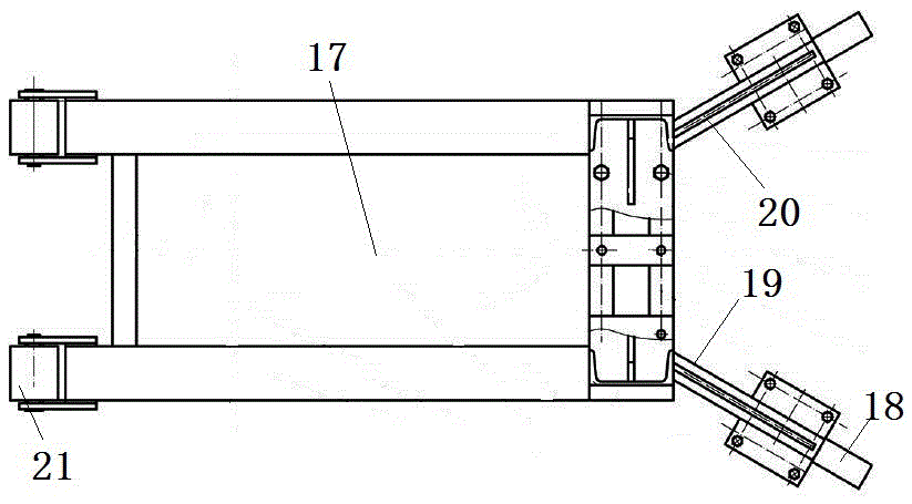
[0021] Such as Figure 1~3 As shown, a circuit breaker mechanism maintenance trolley includes a gantry 1, and a lifting body 2 is arranged on the gantry. A rotating body 3 is arranged on the lifting body, and the lifting body drives the rotating body to rotate through the electric mechanism, and a docking beam 4 for docking with the circuit breaker mechanism is arranged on the rotating body.

[0022] In the embodiment of the present invention, the driving mechanism includes a hand wheel 5 arranged on the gantry, and the output end of the hand wheel is connected with a vertically arranged ball screw pair 6 through a worm gear mechanism. The rod pair is fixedly connected with the lifting body.

[0023] In the embodiment of the present invention, the electric me...


PUM


Abstract

The invention relates to a breaker mechanism maintenance trolley. The breaker mechanism maintenance trolley comprises a gantry, the gantry is provided with an ascending and descending body, the end, connected with the gantry, of the ascending and descending body is driven by a driving mechanism to perform ascending and descending movement, the ascending and descending body is provided with a rotary body and drives the rotary body to rotate through an electric mechanism, and the rotary body is provided with a butt-joint beam used for being in butt joint with a breaker mechanism. The breaker mechanism maintenance trolley is simple in structure, and the breaker mechanism can be in threaded connected with the butt-joint beam of the rotary body, so that the horizontal height and angle of the breaker mechanism are adjusted to the proper maintenance position, efficiency is high, safety and convenience are achieved, and time and labor are saved.

Description

technical field [0001] The invention relates to a circuit breaker mechanism maintenance trolley. Background technique [0002] During the dismantling and overhaul of the circuit breaker mechanism, it is necessary to remove and install bearings, ratchets, circlips and other accessories from different angles of the movement. In particular, some accessories have small disassembly space and limited angles, requiring multiple people to rotate the heavy movement to the required installation angle without shaking, and then one person disassembles and assembles the accessories. Since the movement is directly placed on the ground or a small platform, the height is low and cannot be adjusted. At the same time, after the mechanism is assembled, it needs to be hoisted several times. Movement; the inspection and maintenance of the circuit breaker mechanism requires the cooperation of multiple people, which is extremely labor-intensive, and even the work cannot be completed when the perso...

Claims


Application Information

Patent Timeline
Patent Type & Authority Applications(China)
IPC IPC(8): B66D3/20B66D3/18
CPCB66D3/18B66D3/20
Inventor 谢鹏
Owner STATE GRID FUJIAN ELECTRIC POWER CO LTD
Why Eureka
Try Eureka