Wheel type movable bearing crowbar

A wheel type and load-bearing wheel technology, which is applied in the direction of crowbars and lifting devices, can solve the problems of inability to use cranes, heavy transformers, and moving obstacles, and achieve the effects of saving manpower and material resources, saving costs, and being easy to move

Inactive Publication Date: 2016-06-15
STATE GRID CORP OF CHINA +1
View PDF8 Cites 2 Cited by
  • Summary
  • Abstract
  • Description
  • Claims
  • Application Information

AI Technical Summary

Problems solved by technology

[0002] At present, it is very difficult for power distribution professionals to replace indoor transformers, because the transformer has a very large weight and relatively small volume, and there are few points on the transformer that can bear force. The most critical factor is during the indoor movement. These factors create great obstacles to movement as the space is too small to use equipment such as cranes

Method used


Image

  • Wheel type movable bearing crowbar

Examples


Embodiment 1

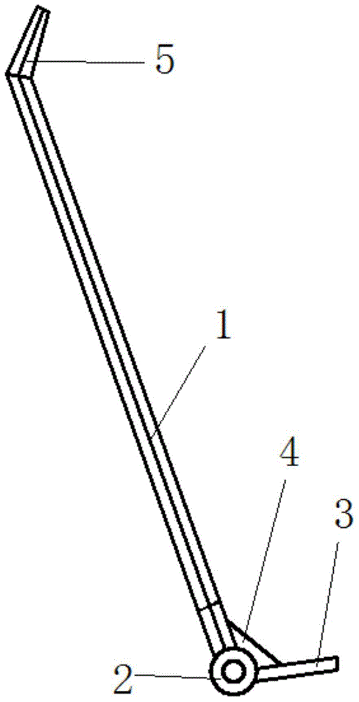
[0015] This embodiment provides a wheel-type load-bearing movable crowbar, which is characterized in that: the wheel-type load-bearing movable crowbar includes a crowbar 1, a load-bearing wheel 2, a crowbar 3, a triangular reinforcing rib 4, a small crowbar plate 5;

[0016] Among them: the bottom of the crowbar 1 is welded to the crowbar 3, and the obtuse angle between them is 100°; two load-bearing wheels 2 are installed at the joint between the crowbar 1 and the crowbar 3; the upper part of the welding part between the bottom of the crowbar 1 and the crowbar 3 is welded There is a triangular reinforcing rib 4; a small crowbar 5 is welded on the top of the crowbar 1, and the obtuse angle between the crowbar 1 and the small crowbar 5 is 100°.

[0017] The load-carrying wheel 2 is a rolling bearing.

[0018] Described skid plate 3 structure is the steel plate of long 150 millimeters, wide 60 millimeters, thick 5 millimeters.

[0019] Described small skid plate 5 structures a...

Embodiment 2

[0022] This embodiment provides a wheel-type load-bearing movable crowbar, which is characterized in that: the wheel-type load-bearing movable crowbar includes a crowbar 1, a load-bearing wheel 2, a crowbar 3, a triangular reinforcing rib 4, a small crowbar plate 5;

[0023] Among them: the bottom of the crowbar 1 is welded to the crowbar 3, and the obtuse angle between them is 100°; two load-bearing wheels 2 are installed at the joint between the crowbar 1 and the crowbar 3; the upper part of the welding part between the bottom of the crowbar 1 and the crowbar 3 is welded There is a triangular reinforcing rib 4; a small crowbar 5 is welded on the top of the crowbar 1, and the obtuse angle between the crowbar 1 and the small crowbar 5 is 100°.

[0024] The load-carrying wheel 2 is a rolling bearing.

[0025] Described skid plate 3 structure is the steel plate of long 150 millimeters, wide 60 millimeters, thick 5 millimeters.

[0026] Described small skid plate 5 structures a...

Embodiment 3

[0029] This embodiment provides a wheel-type load-bearing movable crowbar, which is characterized in that: the wheel-type load-bearing movable crowbar includes a crowbar 1, a load-bearing wheel 2, a crowbar 3, a triangular reinforcing rib 4, a small crowbar plate 5;

[0030] Among them: the bottom of the crowbar 1 is welded to the crowbar 3, and the obtuse angle is 115°; two load-bearing wheels 2 are installed at the connection between the crowbar 1 and the crowbar 3; the upper part of the welding part of the bottom of the crowbar 1 and the crowbar 3 is welded There is a triangular reinforcing rib 4; the top of the crowbar 1 is welded with a small crowbar 5, and the obtuse angle between the crowbar 1 and the small crowbar 5 is 115°.

[0031] The load-carrying wheel 2 is a rolling bearing.

[0032] Described skid plate 3 structure is the steel plate of long 150 millimeters, wide 60 millimeters, thick 5 millimeters.

[0033] Described small skid plate 5 structures are long 100...


PUM


Abstract

The invention discloses a wheel type movable bearing crowbar. The wheel type movable bearing crowbar is characterized in that the wheel type movable bearing crowbar comprises a crowbar body, bearing wheels, a crow plate, a triangular reinforcing rib and a small crow plate, wherein the bottom of the crowbar body is welded to the crow plate, and the obtuse angle formed between the crowbar body and the crow plate is 95-115 degrees; the two bearing wheels are installed at the joint of the crowbar body and the crow plate; the triangular reinforcing rib is welded to the upper portion of the welded joint of the bottom of the crowbar body and the crow plate; and the small crow plate is welded to the top of the crowbar body, and the obtuse angle between the crowbar body and the small crow plate is 95-115 degrees. The wheel type movable bearing crowbar has the advantages that the principle structure is simple, usage is convenient, large equipment such as transformers can be pried, and the crowbar is convenient to move; and meanwhile, due to the small crow plate arranged at the other end of the crowbar body, small equipment can be pried conveniently, the work efficiency is improved, manpower and material resources are saved, and much cost is reduced.

Description

technical field [0001] The invention relates to the structural field of displacement construction tools after large-scale mechanical equipment is separated from a crane, in particular to a wheel-type load-bearing movable crowbar. Background technique [0002] At present, for power distribution professionals, it is very difficult to replace the indoor transformer, because the transformer has a very large weight and relatively small volume, and there are few points on the transformer that can bear force. The most critical factor is during the indoor movement. These factors present a great obstacle to movement as the space is too small to use equipment such as cranes. Contents of the invention [0003] The purpose of the present invention is to facilitate the portable and rapid movement of the transformer indoors, and a wheel-type load-bearing movable crowbar is specially provided. [0004] The invention provides a wheel-type load-bearing movable crowbar, which is characteri...

Claims


Application Information

Patent Timeline
Patent Type & Authority Applications(China)
IPC IPC(8): B66F15/00
Inventor 李占柱王振维李飞郭崇鹏
Owner STATE GRID CORP OF CHINA
Why Eureka
Try Eureka