All-cutting-edge knife flywheel

A cutter wheel and cutting edge technology, applied in the field of full-edge cutter wheel, can solve the problems of poor rotation of cutter wheel and large impact force of cutter wheel, so as to reduce the rate of defective cutting quality, improve impact resistance, and reduce friction area. Effect

Active Publication Date: 2016-06-15
BEIJING WORLDIA DIAMOND TOOLS
View PDF6 Cites 8 Cited by
  • Summary
  • Abstract
  • Description
  • Claims
  • Application Information

AI Technical Summary

Problems solved by technology

[0005] The purpose of the present invention is to provide a full-edge cutter wheel to solve the problem of the relatively large impact force received by the existing cutter wheel during the cutting process, as well as the sharp angles formed between the disk surfaces on both sides and the first inclined plane and the second inclined plane. The problem caused by the poor rotation of the cutter wheel

Method used


Image

  • All-cutting-edge knife flywheel
  • All-cutting-edge knife flywheel
  • All-cutting-edge knife flywheel

Examples


Embodiment 1

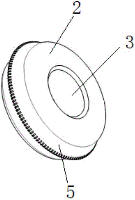
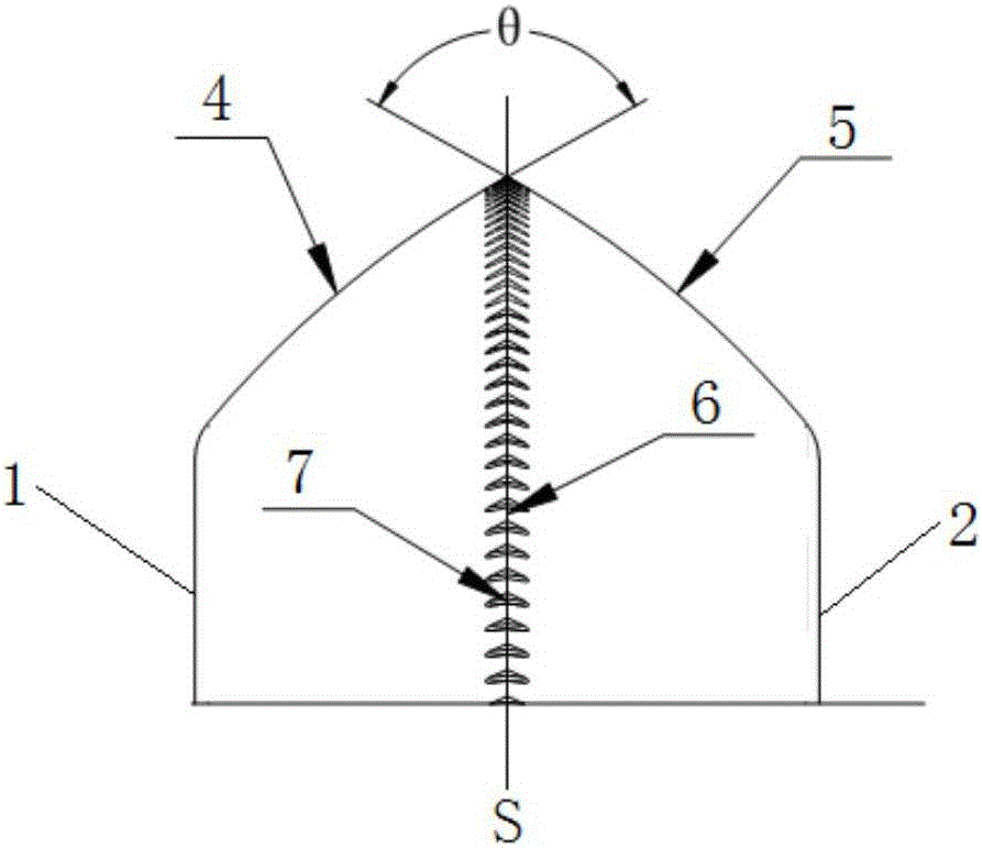
[0061] The structures of the first curved surface and the second curved surface in this embodiment are as follows figure 1 shown. The first curved surface 4 and the second curved surface 5 are symmetrical about the longitudinal center section of the cutter wheel. Wherein, the first curved surface 4 and the second curved surface 5 are both first convex arc surfaces. Wherein, the radius of the first convex arc surface is 0.75-0.9 mm. The central angle of the arc cut by the convex arc surface by the first central section is 20-70 degrees. The angle between the tangent line at the intersection of the first curved surface 4 and the circumferential cutting edge 6 and the tangent line at the intersection of the second curved surface 5 and the circumferential cutting edge 6 is 90-160 degrees.

[0062] It should be noted that the first central section mentioned in this application is a plane that can simultaneously cut the first curved surface, the second curved surface, the first c...

Embodiment 2

[0065] Figure 4 It is a schematic structural view of a full-blade cutter wheel according to a preferred embodiment. Such as Figure 4 As shown, the first curved surface 4 and the second curved surface 5 are symmetrical about the longitudinal center section of the cutter wheel. Wherein, both the first curved surface 4 and the second curved surface 5 include a second convex arc surface 40 and a first inclined surface 41 .

[0066] On the first curved surface 4 , one edge of the second convex arc surface 40 is connected to the first cutter wheel disc surface 1 ; the other edge of the first convex arc surface is connected to the first inclined surface 41 . On the second curved surface 5 , one edge of the second convex arc surface 40 is connected to the second cutter wheel disc surface 2 ; the other edge of the first convex arc surface is connected to the first inclined surface 41 . The other edge of the first inclined surface 41 on the first curved surface 4 intersects with th...

Embodiment 3

[0070] Figure 5 It is a partial structural schematic diagram of a full edge cutter wheel shown according to a preferred embodiment. Such as Figure 5 As shown, the first curved surface 4 and the second curved surface 5 are symmetrical about the longitudinal center section of the cutter wheel. Wherein, both the first curved surface 4 and the second curved surface 5 include a third convex arc surface 42 and a first concave arc surface 43 .

[0071] On the first curved surface 4 , one edge of the third convex arc surface 42 is connected to the first cutter wheel disk 1 , and the other edge of the third convex arc surface 42 is connected to an edge of the first concave arc surface 43 . On the second curved surface 5 , one edge of the third convex arc surface 42 is connected to the second cutter wheel disc surface 2 , and the other edge of the third convex arc surface 42 is connected to an edge of the first concave arc surface 43 . The other edge of the first concave arc surfac...


PUM

PropertyMeasurementUnit
radiusaaaaaaaaaa
radiusaaaaaaaaaa
radiusaaaaaaaaaa

Abstract

The embodiment of the invention discloses an all-cutting-edge knife flywheel which comprises a first knife flywheel disk surface, a second knife flywheel disk surface and a shaft hole, wherein the shaft hole is positioned at the center of the knife flywheel and extends along the transverse direction. The all-cutting-edge knife flywheel comprises a first curved surface and a second curved surface, wherein the first curved surface extends to the longitudinal center cross section of the knife flywheel along the outer edge of the first knife flywheel disk surface and forms smooth transition with the outer edge of the first knife flywheel disk surface; and the second curved surface extends to the longitudinal center cross section of the knife flywheel along the outer edge of the second knife flywheel disk surface, and forms smooth transition with the intersection line of the outer edge of the first knife flywheel disk surface. The intersection line of the first curved surface and the second curved surface at the longitudinal center cross section of the knife flywheel forms the circumferential cutting edge. The circumferential cutting edge is uniformly distributed with a groove. A groove inner cutting edge is arranged in the groove. According to the all-cutting-edge knife flywheel, the two side disk surfaces and the two curved surfaces for forming the circumferential cutting edge do not form sharp angles, thereby enhancing the impact resistance of the knife flywheel, lowering the friction area between the two side disk surfaces of the knife flywheel and the knife rest inner wall, and reducing the resistance in the knife flywheel rotation process.

Description

technical field [0001] The invention relates to the technical field of tool processing, in particular to a full-edge cutter wheel. Background technique [0002] With the diversified development of glass products, many production fields require glass to be thinner and harder, and the requirements for glass cutting quality are getting higher and higher. The tools for cutting glass are generally disk-shaped cutter wheels. The common features of the cutter wheels that have been used for a long time on the market are: they all include a cutting edge, a cutter wheel disk surface, and a shaft hole in the center of the cutter wheel for installing the cutter shaft. [0003] The cutting edge of the existing cutter wheel is in an inverted V shape, formed by the intersection of the first inclined plane and the second inclined plane, and the intersection line between the first inclined plane and the second inclined plane is the circumferential cutting edge of the cutter wheel. The first...

Claims


Application Information

Patent Timeline
Patent Type & Authority Applications(China)
IPC IPC(8): C03B33/10
CPCC03B33/10B28D1/041C03B33/027C03B33/033
Inventor 唐文林
Owner BEIJING WORLDIA DIAMOND TOOLS
Why Eureka
Try Eureka