Bearing-rail beam low track and viaduct transition section structure of medium-low-speed magnetic suspension traffic engineering

A technology of traffic engineering and low-level lines, which is applied to roads, bridges, tracks, etc., can solve problems affecting the smoothness of F-rail, difficult quality control, and wrong platform of F-rail, so as to avoid local pressure damage and achieve ride comfort Requirements, the effect of reducing the braking impact force

Active Publication Date: 2016-06-15
CHINA RAILWAY SIYUAN SURVEY & DESIGN GRP
View PDF7 Cites 24 Cited by
  • Summary
  • Abstract
  • Description
  • Claims
  • Application Information

AI Technical Summary

Problems solved by technology

In the low-lying line section, the foundation under the rail-bearing beam is a geotechnical structure composed of rock and soil. Affected by factors such as terrain and geological conditions, the quality is relatively difficult to control. It is prone to uneven settlement under the action of load and various natural environmental factors. It is inevitable that post-construction settlement inconsistent with the abutment of the elevated structure will occur, resulting in poor post-construction settlement. The settlement difference between the low-lying line and the position of the abutment will inevitably affect the smoothness of the F track, and may even cause the F track to be misplaced and deformed And other problems, when severe, will affect the normal operation of maglev vehicles
Therefore, the subgrade treatment method of the high-speed railway transition section cannot be directly used in maglev traffic engineering

Method used


Image

  • Bearing-rail beam low track and viaduct transition section structure of medium-low-speed magnetic suspension traffic engineering
  • Bearing-rail beam low track and viaduct transition section structure of medium-low-speed magnetic suspension traffic engineering
  • Bearing-rail beam low track and viaduct transition section structure of medium-low-speed magnetic suspension traffic engineering

Examples


Embodiment Construction

[0027] In order to make the object, technical solution and advantages of the present invention clearer, the present invention will be further described in detail below in conjunction with the accompanying drawings and embodiments. It should be understood that the specific embodiments described here are only used to explain the present invention, not to limit the present invention. In addition, the technical features involved in the various embodiments of the present invention described below can be combined with each other as long as they do not constitute a conflict with each other.

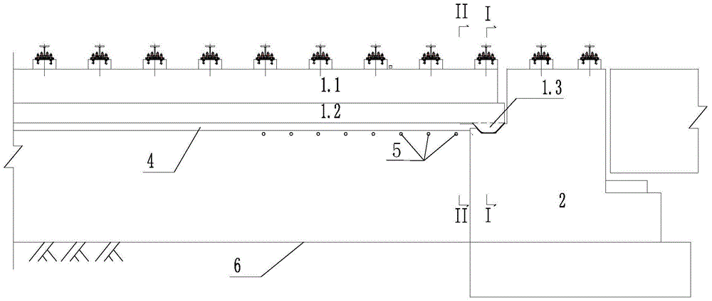
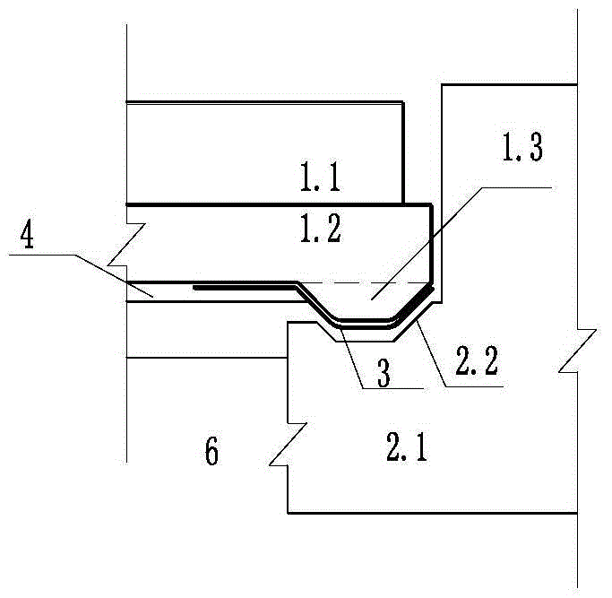
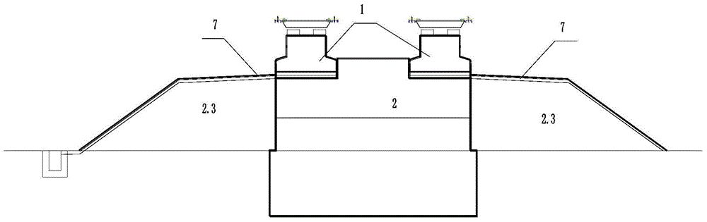
[0028] refer to Figure 1 to Figure 5 , a low-speed magnetic levitation traffic engineering rail bearing beam 1 low line and viaduct transition section structure, including roadbed, bridge abutment 2, rail bearing beam 1, grouting pipe 5 and drainage ditch 7, wherein,

[0029] The bridge abutment 2 includes an abutment back main body 2.1 and an abutment cone 2.3, the abutment back main body 2.1...


PUM


Abstract

The invention discloses a bearing-rail beam low track and viaduct transition section structure of medium-low-speed magnetic suspension traffic engineering. The structure comprises a roadbed, a bridge abutment, bearing-rail beams, a plurality of grouting pipes and drainage ditches. The bridge abutment comprises an abutment back body and abutment cones. Each bearing-rail beam comprises a bottom slab and an upper structure arranged on the bottom slab, and the bottom slab is buried in the roadbed and extends downwards to form tenons corresponding to tenon grooves. Each tenon is placed in the corresponding tenon groove, and round corners are arranged on the tenons and the tenon grooves so that the tenons can rotate in the tenon grooves. The grouting pipes are arranged in the roadbed. According to the bearing-rail beam low track and viaduct transition section structure, the bearing-rail beams of a low track are in lap joint with the tenon grooves of a viaduct, so that settlement and slab staggering, caused by different foundation treatment measures, between the low track and the viaduct are avoided, the effect that settlement and slab staggering of a magnetic levitation F rail at the junction of the low track and the abutment are avoided is guaranteed, and the requirement for smoothness of the F rail at the transition section between a viaduct structure and the low track of the magnetic suspension traffic engineering is effectively met.

Description

technical field [0001] The invention belongs to the field of low-set line structures of medium and low-speed maglev traffic engineering, and more specifically relates to a transition section structure between low-set track beams and viaducts of medium-low speed maglev traffic engineering. Background technique [0002] Medium and low-speed maglev rail transit is a new type of transportation. At present, there are few research results at home and abroad, and there are even fewer lines in operation around the world. At present, there are only the commercial operation line of the medium and low speed maglev railway in Japan in March 2005-Eastern Hills Line and the commercial operation line of the medium and low speed maglev railway in South Korea in June 2014. At present, China's medium and low-speed maglev transportation only has the National University of Defense Technology test line, the Qingchengshan test line, and the Tangshan test line, but there are no official lines in o...

Claims


Application Information

Patent Timeline
Patent Type & Authority Applications(China)
IPC IPC(8): E01B25/30E01D19/02
CPCE01B25/30E01D19/02
Inventor 郭建湖李小和姚洪锡王勇刚杨辉建李巍
Owner CHINA RAILWAY SIYUAN SURVEY & DESIGN GRP
Why Eureka
Try Eureka