Cast-in-situ cavity floor system by using ribbed steel mesh plate

A technology of cavity floor and ribbed steel mesh, which is used in floors, building components, buildings, etc.

Inactive Publication Date: 2016-06-15
王本淼 +2
View PDF11 Cites 2 Cited by
  • Summary
  • Abstract
  • Description
  • Claims
  • Application Information

AI Technical Summary

Problems solved by technology

The new technology of cast-in-place cavity floor is realized by using ribbed steel mesh, and the unsealed ribbed steel mesh is used to replace the existing fully sealed hollow filling body or polystyrene foam solid filling body, and various plates will be used to make The supporting steel mesh filling body is transformed and upgraded, the existing cast-in-place cavity floor hole-forming technology is optimized, and the defect that any filling body in the existing cavity floor hole-forming technology cannot work with the floor to bear force is overcome. At the same time, Increased fire rating of the entire building

Method used


Image

  • Cast-in-situ cavity floor system by using ribbed steel mesh plate
  • Cast-in-situ cavity floor system by using ribbed steel mesh plate
  • Cast-in-situ cavity floor system by using ribbed steel mesh plate

Examples


Embodiment Construction

[0020] The invention will be further described below in conjunction with the accompanying drawings.

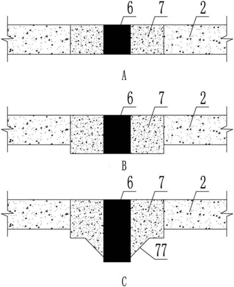
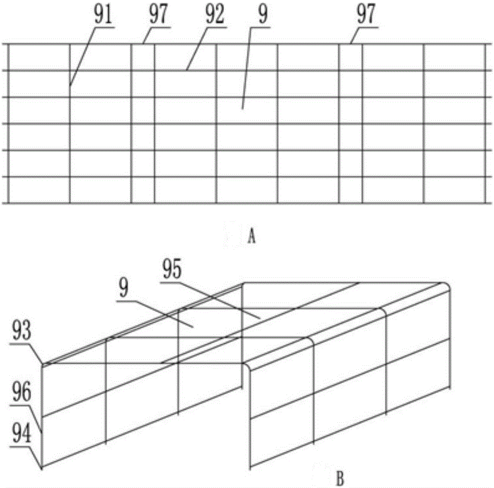
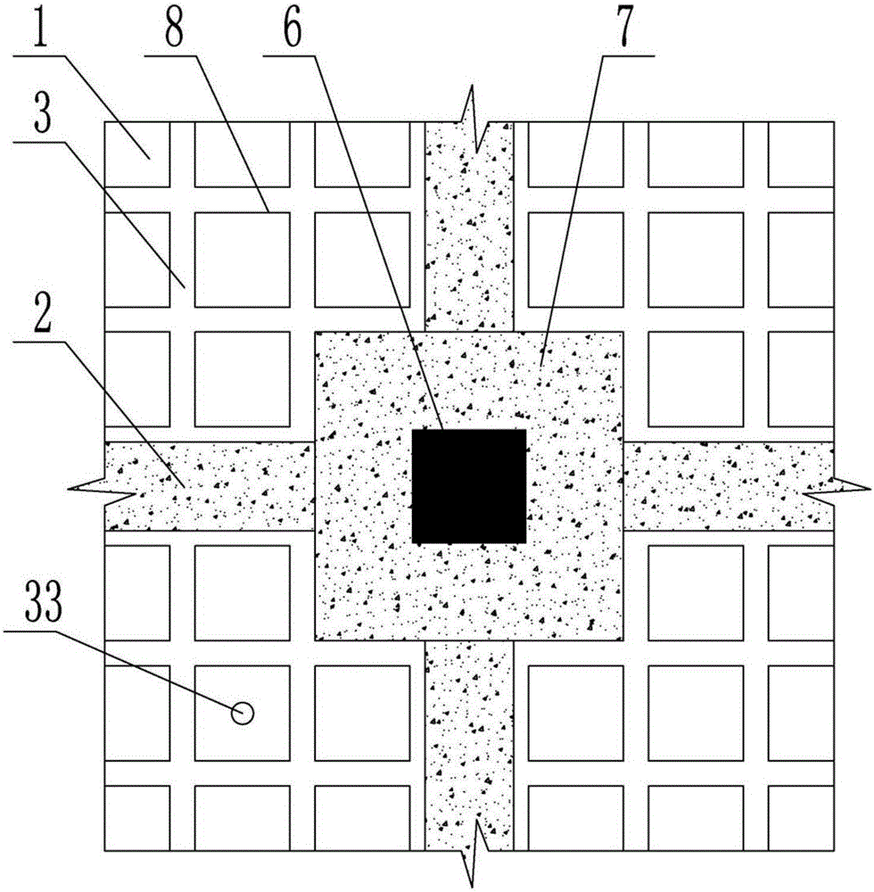
[0021] figure 1It is a plane structure diagram of a cavity floor cast-in-place hollowed out with ribbed steel mesh according to the present invention. When the present invention is implemented, floor steel bars are laid on the cavity floor formwork with an "I-shaped" stress section, and the rib steel bars are bound 3. Bind the main beam reinforcement 2 and the column reinforcement 6 to form a column network; add auxiliary reinforcement at the junction of the column 6 and the main beam 2 to resist shearing, forming a structural platform 7 between the column 6 and the main beam 2; Bind into a grid of rib beams, and arrange ribbed steel mesh 8 in the grid of rib beam 3. The ribbed steel mesh 8 is made according to the required specifications and sizes of architectural design. The technology of the present invention is all made of mechanized metal materials. Ribbed steel mesh eng...


PUM


Abstract

The present invention provides a cast-in-situ cavity floor system by using a ribbed steel mesh plate. The cast-in-situ cavity floor system is composed of a main beam, a ribbed beam, a top flange plate, a bottom flange plate, a column and beam structure platform, and a ribbed steel mesh plate; the column and beam structure platform is an inapparent platform, or an apparent platform, or a taper platform; a steel mesh body of the ribbed steel mesh plate is disposed in concrete of the bottom flange plate in a situ casting manner; the ribbed steel mesh plate is composed of a plate mesh, a plate end mesh and a support mesh; the plate mesh, the plate end mesh and the support mesh are all prepared by pure metal materials; the plate mesh forms the periphery of the ribbed steel mesh plate; the steel mesh body includes steel plate expansion meshes, a V-shaped rib and a turning connecting piece; the expansion meshes at two sides of the turning connecting piece are not in the same direction; and the support mesh is a steel mesh body or a reinforcing mesh body. The cavity floor system is casted by using the ribbed steel mesh plate, concrete mortar directly wraps the ribbed steel mesh plate to bear force and commonly prevent crack, and the defect of a current hollow floor system technology is effectively solved.

Description

technical field [0001] The invention relates to a technology of a cast-in-place reinforced concrete cavity floor, in particular to a technology of a cavity floor cast-in-place with a ribbed steel mesh. Background technique [0002] At present, in the field of cast-in-place reinforced concrete hollow floor technology, a fully sealed filling body component is usually used to form a hollow floor, such as the ZL98231113.3 concrete thin-walled cylinder component declared by the inventor, which is made into a sealed cylindrical filling body. In order to realize the cast-in-place hollow floor, a tubular hollow filling body is provided, which solves the technical problem of non-centering hole formation in the cast-in-place hollow floor. However, due to the sealed tubular hollow filling body, there are defects such as difficult fixing, high buoyancy, high density and heavy weight, inconvenient production, transportation and on-site construction, low evacuation rate, and inability to ...

Claims


Application Information

Patent Timeline
Patent Type & Authority Applications(China)
IPC IPC(8): E04B5/36E04B1/21
CPCE04B5/36E04B1/21
Inventor 王海崴王本淼马锋杨建军
Owner 王本淼
Why Eureka
Try Eureka