A pump lock device

A lock device and pump lock technology, applied in the field of medical equipment, can solve the problems of heavy plug-in box structure, user misoperation, and users cannot identify the locking mechanism, etc., and achieve the effect of thin thickness, prevent misoperation, and compact overall structure

Active Publication Date: 2018-05-15
SHENZHEN MINDRAY SCIENTIFIC CO LTD
View PDF10 Cites 0 Cited by
  • Summary
  • Abstract
  • Description
  • Claims
  • Application Information

AI Technical Summary

Problems solved by technology

[0002] Existing pump lock devices usually only have locking and unlocking functions, and users cannot identify the state of the locking mechanism through the external handle, which is likely to cause user misoperation
In addition, the existing unlocking mechanism with push-out function is often too large in the push-out direction, resulting in a very thick structure of the plug-in box

Method used


Image

  • A pump lock device
  • A pump lock device
  • A pump lock device

Examples


Embodiment Construction

[0024] The technical solutions in the embodiments of the present invention will be clearly and completely described below in conjunction with the accompanying drawings in the embodiments of the present invention. Obviously, the described embodiments are only a part of the embodiments of the present invention, rather than all the embodiments. Based on the embodiments of the present invention, all other embodiments obtained by those of ordinary skill in the art without creative work shall fall within the protection scope of the present invention.

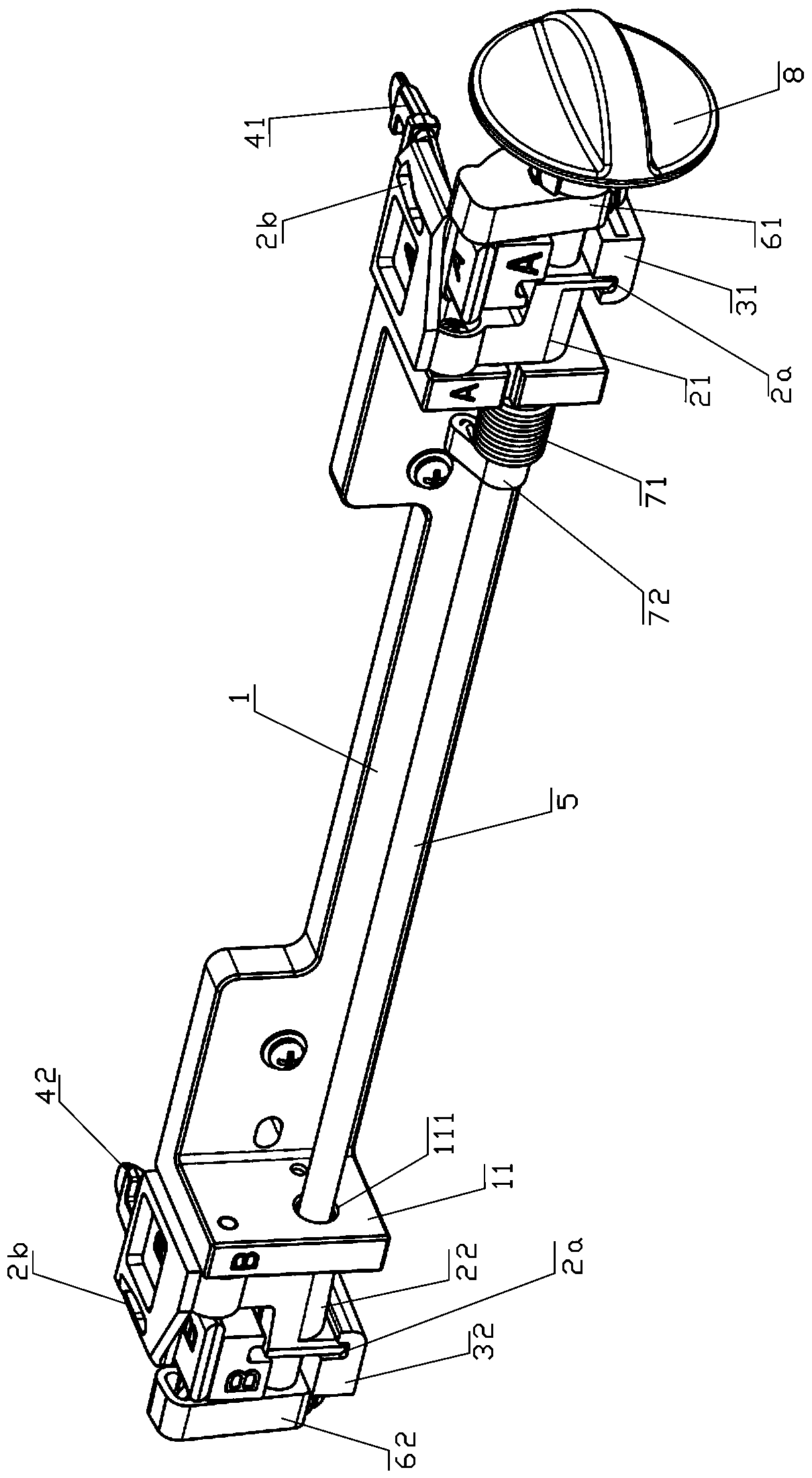
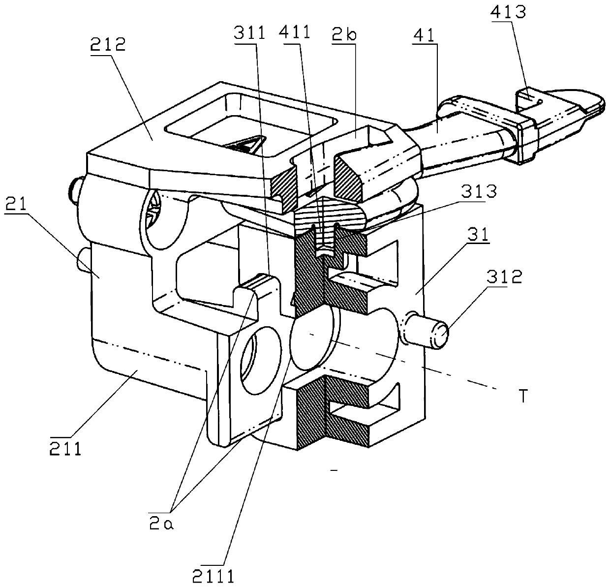
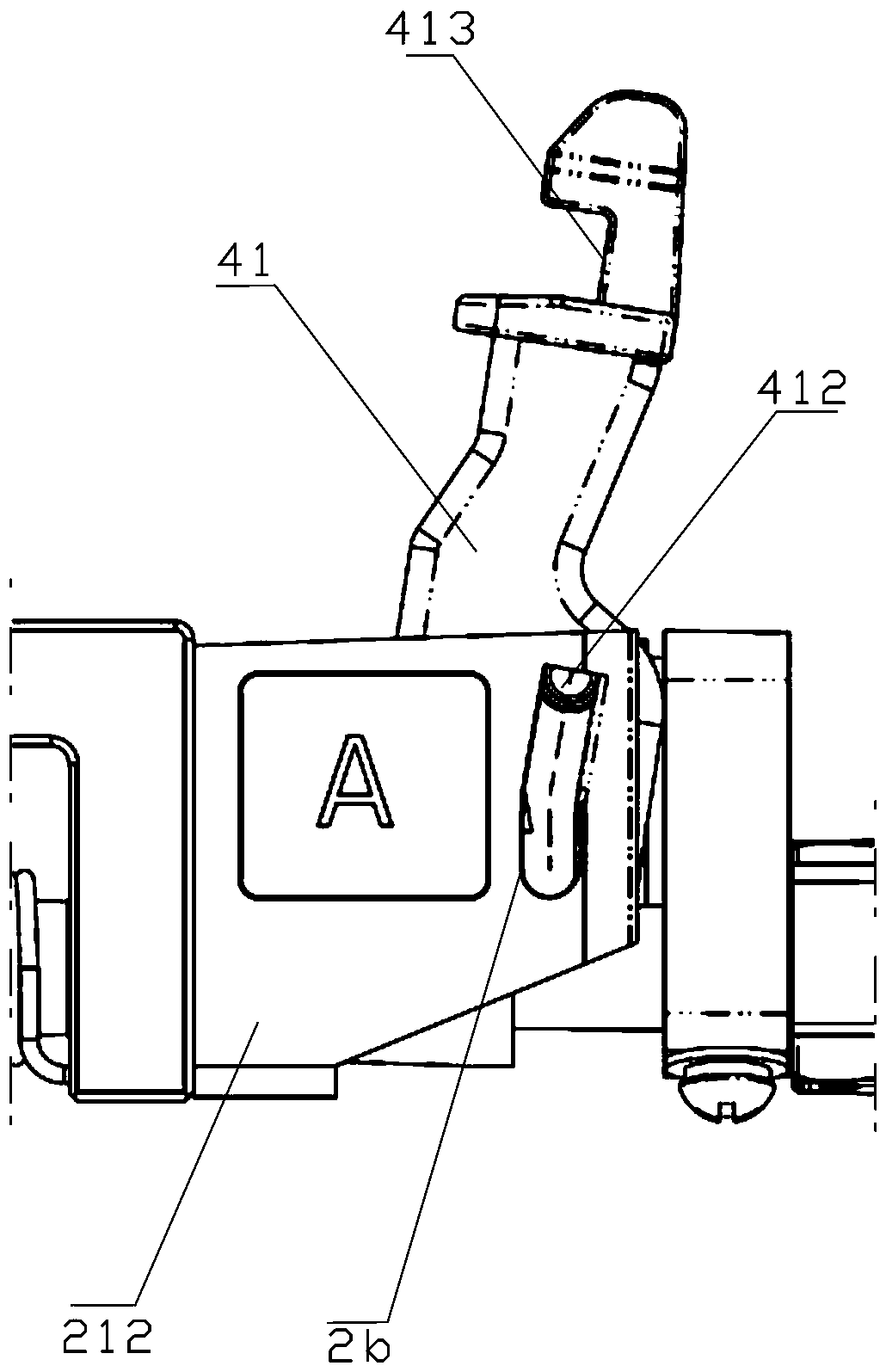
[0025] See also Figure 1-Figure 5 Shown is the first embodiment of the pump lock device of the present invention.

[0026] The pump lock device in this embodiment includes: a bracket 1, a first fixing block 21 and a second fixing block 22 mounted on the bracket 1, a first sliding block 31 and a second sliding block 32, and a first locking hook 41 and Second lock hook 42.

[0027] Wherein: the first fixed block 21 and the second fixed block...


PUM


Abstract

The invention discloses a pump lock device. The pump lock device comprises a supporting frame, a fixed block, a sliding block and a lock hook, wherein the fixed block, the sliding block and the lock hook are arranged on the supporting frame; a first guide part and a second guide part are arranged on the fixed block; the sliding block is arranged on the first guide part; and one side of the lock hook is rotationally connected with the sliding block, and the other side of the lock hook is limited in the second guide part. External force drives the sliding block to move along the first guide part, and the lock hook is in linkage with the sliding block and carries out push-in unlocking or push-in locking along the second guide part. By means of the pump lock device, the functions of pushing in a pump body for locking and pushing out the pump through rotation of a knob are realized, and the locking state can be indicated through the external knob. The pump lock device has a compact structure and a small thickness.

Description

Technical field [0001] The invention relates to the field of medical equipment, and in particular to a pump lock device used to fix the position of an infusion pump and ensure the connection of the infusion pump in an infusion management system. Background technique [0002] Existing pump lock devices usually only have locking and unlocking functions, and users cannot identify the state of the locking mechanism through an external handle, which may easily cause misoperation by users. In addition, the existing unlocking mechanism with the push-out function is often too large in the push-out direction, causing the structure of the plug-in box to become very heavy. Summary of the invention [0003] The technical problem to be solved by the present invention is to provide a pump lock device, which realizes the functions of pushing the pump body to lock and pushing the pump out by rotating the knob; it has a compact structure and a thinner thickness. [0004] In order to solve the above...

Claims


Application Information

Patent Timeline
Patent Type & Authority Patents(China)
IPC IPC(8): F04B53/00
Inventor 孙亮刘华勇郑宏
Owner SHENZHEN MINDRAY SCIENTIFIC CO LTD
Why Eureka
Try Eureka