Drawer type box body structure and dish washing machine
A box structure and drawer-type technology, which is applied in the field of drawer-type box structure and dishwashers, can solve the problems of the dishwasher not being closed normally, the dishwasher being damaged, and the operator being injured, so as to avoid equipment damage and ensure safety. Risk, labor-saving and convenient operation, and the effect of reducing the intensity of operation
- Summary
- Abstract
- Description
- Claims
- Application Information
AI Technical Summary
Problems solved by technology
Method used
Image
Examples
Embodiment 1
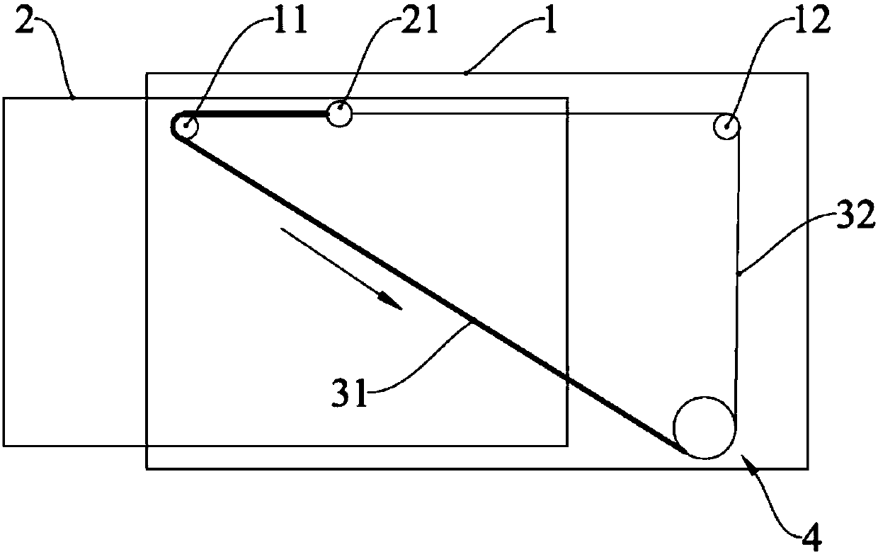
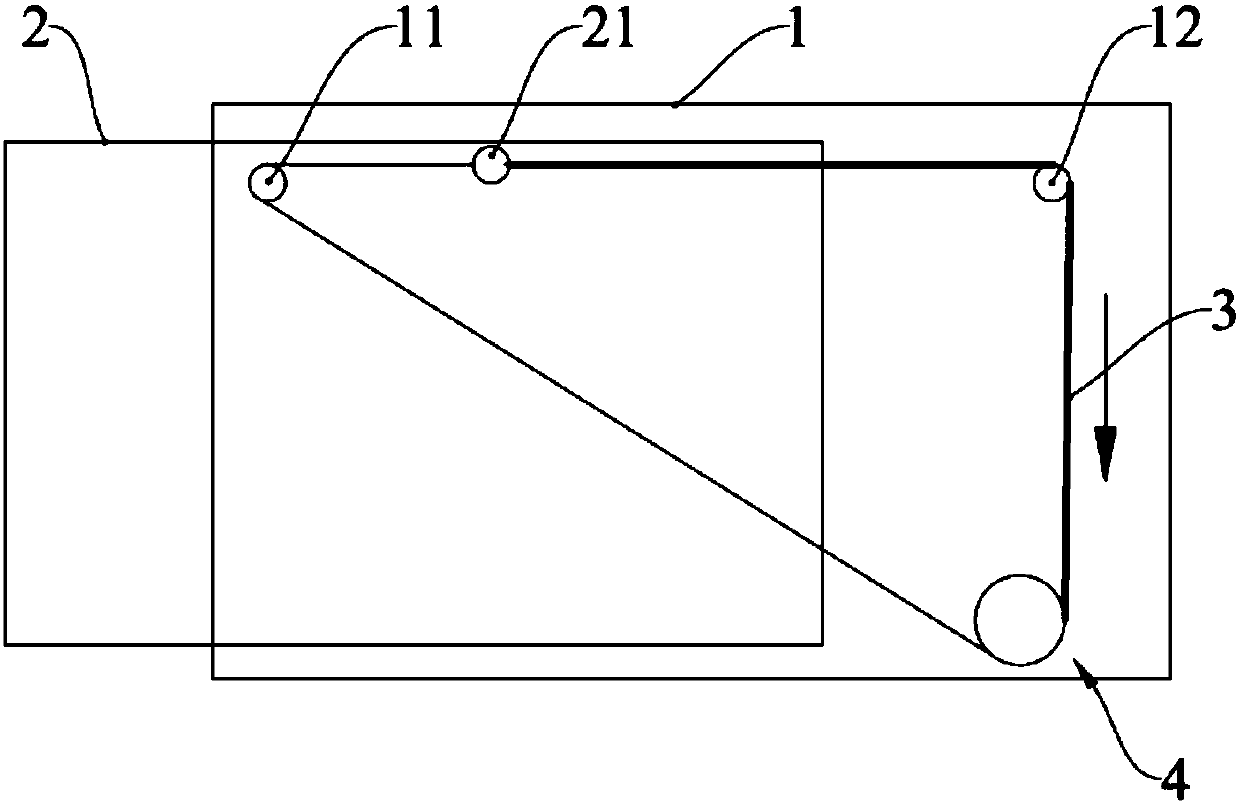
[0037] This embodiment provides a dishwasher, which includes a drawer box structure, specifically, such as Figure 1-Figure 2 As shown, the drawer box structure includes a box body 1 and a drawer 2 arranged in the box body 1. The box body 1 is the main part of the dishwasher. One side of the box body 1 is opened, and the drawer 2 is arranged on the box body through the opening. within 1. When the drawer 2 was pulled out of the casing 1, the tableware could be put into the drawer 2, and then the drawer 2 was pushed into the casing 1, and the end of the drawer 2 was used as a door to close the opening of the casing 1, so as to clean the tableware.
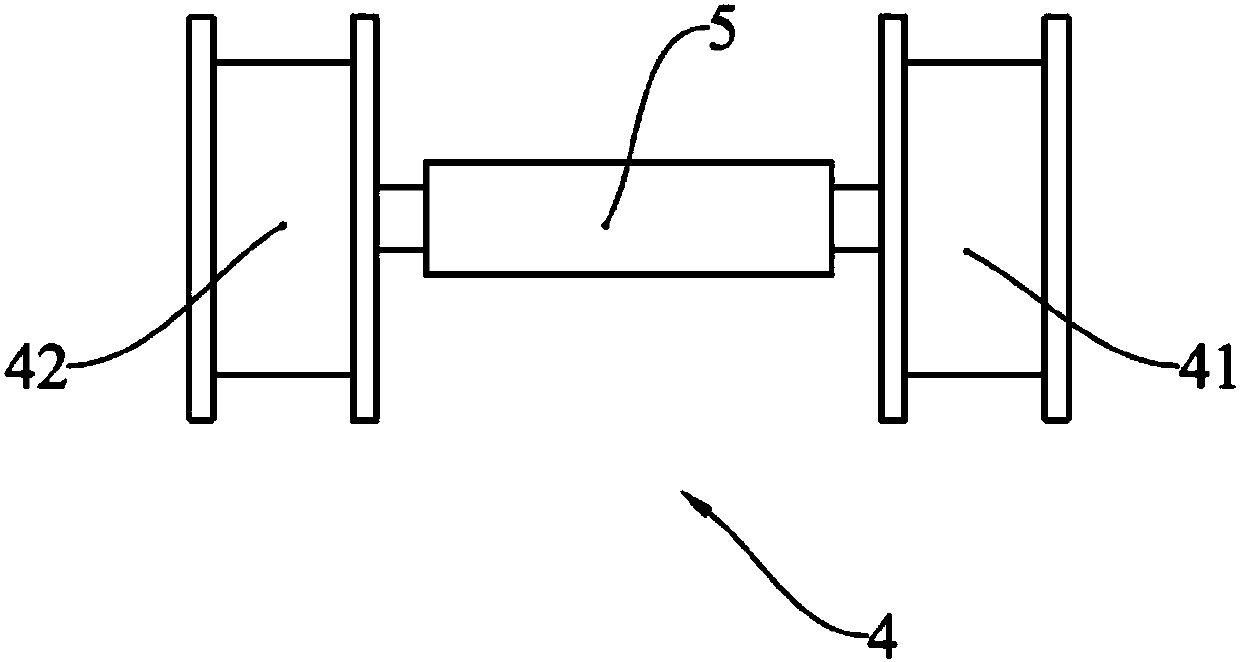
[0038] Since the overall weight of the drawer 2 increases after the tableware is placed in the drawer 2, it is laborious to pull it out or push it in manually. For the convenience of the user, the drawer 2 in this embodiment can be automatically pulled out or pushed in, which is labor-saving and easy to operate. , which reduces the ...
Embodiment 2
[0054] This embodiment provides a dishwasher, which includes a drawer-type box structure, and its structure is roughly the same as that of Embodiment 1. The difference from Embodiment 1 is that the wire wheel assembly in this embodiment only uses one wire rope 3 .
[0055] Such as Figure 4 As shown, specifically, when the wire rope 3 is arranged, one end of the wire rope 3 is wound on the first wire pulley 41, and the other end of the wire rope 3 is wound around the second shaft 12 and the first shaft 11 in turn and then wound on the second wire. on the wheel 42, and the middle part of the wire rope 3 is fixed with the fixed end 21. When the wire wheel assembly 4 rotated, one of the first wire wheel 41 and the second wire wheel 42 rotated to take up the wire, and the other rotated to release the wire. One end of the wire rope 3 was tightened, and the other end was loosened, so that the wire rope 3 was driven by a wire wheel. Move to another wire wheel, and in the process of...
PUM
 Abstract
Description
Claims
Application Information
 - R&D
- Intellectual Property
- Life Sciences
- Materials
- Tech Scout
- Unparalleled Data Quality
- Higher Quality Content
- 60% Fewer Hallucinations
Browse by: Latest US Patents, China's latest patents, Technical Efficacy Thesaurus, Application Domain, Technology Topic, Popular Technical Reports.
© 2025 PatSnap. All rights reserved.Legal|Privacy policy|Modern Slavery Act Transparency Statement|Sitemap|About US| Contact US: help@patsnap.com


