
Oil quantity detection method

A detection method and technology of oil quantity, which is applied to liquid level indicators for physical variable measurement, etc., can solve problems such as inaccurate calculation of oil quantity, and achieve the effect of improving accuracy

Active Publication Date: 2019-02-01
大陆汽车车身电子系统(芜湖)有限公司
View PDF4 Cites 0 Cited by
  • Summary
  • Abstract
  • Description
  • Claims
  • Application Information

AI Technical Summary

Problems solved by technology

The traditional algorithm of determining the oil volume based solely on the current measured resistance value will cause the problem of inaccurate calculation of the oil volume.

Method used


Image

  • Oil quantity detection method
  • Oil quantity detection method
  • Oil quantity detection method

Examples


Embodiment Construction

[0016] In the following description, numerous specific details are set forth in order to enable those skilled in the art to fully understand the present invention. It will be apparent, however, to one skilled in the art that the present invention may be practiced without some of these specific details. Furthermore, it should be understood that the invention is not limited to the particular embodiments described. Instead, it is conceivable to implement the present invention in any combination of the following features and elements, regardless of whether they relate to different embodiments. Accordingly, the following aspects, features, embodiments and advantages are by way of illustration only and should not be considered elements or limitations of the claims unless explicitly stated in the claims.

[0017] As mentioned in the aforementioned prior art, the resistance of the oil sensor may change due to corrosion or the like. According to the research of the inventors of the p...


PUM


Abstract

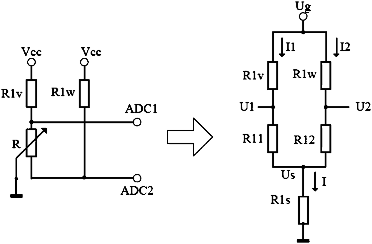
An oil mass detection method comprises the steps of building a circuit model, wherein the circuit model comprises an equivalent resistor corresponding to a slide rheostat of an oil mass sensor and an equivalent resistor corresponding to slide rheostat resistance changes; one end of the equivalent resistor corresponding to slide rheostat resistance changes is grounded, and the other end is connected with a terminal of a slide rheostat sliding contact in the circuit model; the position of the sliding contact is related to present liquid level of a fuel tank; the method also comprises the following steps: measuring voltages on two ends of the slide rheostat; calculating present resistance of the equivalent resistor of the slide rheostat in the circuit model according to the measured voltages and initial total resistance of the slide rheostat; obtaining present oil mass according to the proportion between the calculated present resistance and the initial total resistance of the slide rheostat. The oil mass detection method can obtain the oil mass approaching to the real value, thus improving oil mass detection accuracy.

Description

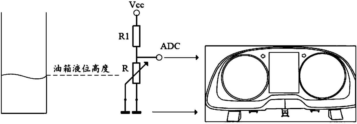
technical field [0001] The invention relates to the development of automobile instrument technology, in particular to an instrument-based oil quantity detection method. Background technique [0002] At present, the fuel quantity in the automobile fuel tank is measured by the fuel quantity sensor in the fuel tank. The principle of the sensor is like a sliding rheostat, and the meter determines the fuel quantity according to the current resistance value. Common fuel level sensors include two-wire sensors and three-wire sensors. [0003] figure 1 It shows the schematic diagram of the principle of realizing oil quantity detection and instrument display through two-wire sensor. refer to figure 1 As shown, the tank liquid level is related to the position of the sliding contact on the sliding rheostat R. The instrument determines the current oil volume (from empty to full) by measuring the resistance between the output ADC and the ground terminal (from 0 to the maximum resistan...

Claims


Application Information

Patent Timeline
Patent Type & Authority Patents(China)
IPC IPC(8): G01F23/24G01F23/22
Inventor 徐洋
Owner 大陆汽车车身电子系统(芜湖)有限公司
Learn More