A gearbox no-load test inertial loading mechanism

A no-load test and loading mechanism technology, which is applied in the direction of machine gear/transmission mechanism testing, etc., can solve the problems that it is difficult to reflect the real quality and performance indicators of the gearbox no-load detection, and cannot completely simulate the rotation of the gearbox with a flywheel, etc., to achieve measurement The effect of authentic and reliable data, accurate docking, and compact overall structure

Inactive Publication Date: 2018-05-18
SHENYANG INST OF AUTOMATION - CHINESE ACAD OF SCI
View PDF5 Cites 0 Cited by
  • Summary
  • Abstract
  • Description
  • Claims
  • Application Information

AI Technical Summary

Problems solved by technology

[0003] The traditional no-load detection work for the assembled gearbox usually only locates the gearbox on the detection mechanism, and then connects the input shaft spline of the gearbox to the docking spline of the driving part of the detection mechanism, and then The gearbox is driven by the drive motor to test the assembly quality and performance of the gearbox under the condition of no external torque. Obviously, the traditional inspection method cannot completely simulate the situation that the gearbox has a flywheel rotating in a real vehicle. The data obtained from the load test is difficult to reflect the real quality and performance indicators of the gearbox no-load test

Method used


Image

  • A gearbox no-load test inertial loading mechanism
  • A gearbox no-load test inertial loading mechanism
  • A gearbox no-load test inertial loading mechanism

Examples


Embodiment Construction

[0025] The present invention will be described in further detail below in conjunction with the accompanying drawings.

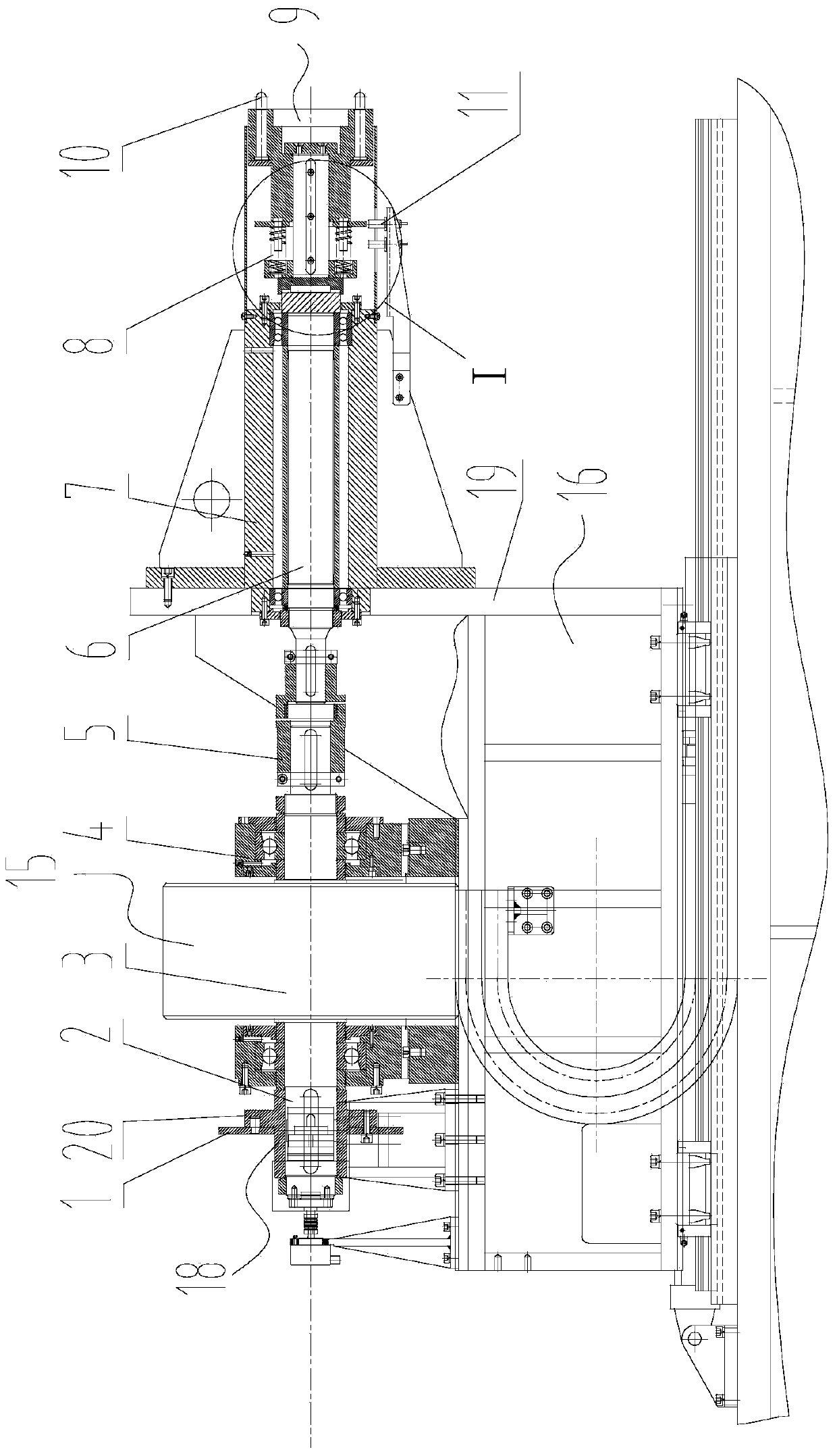
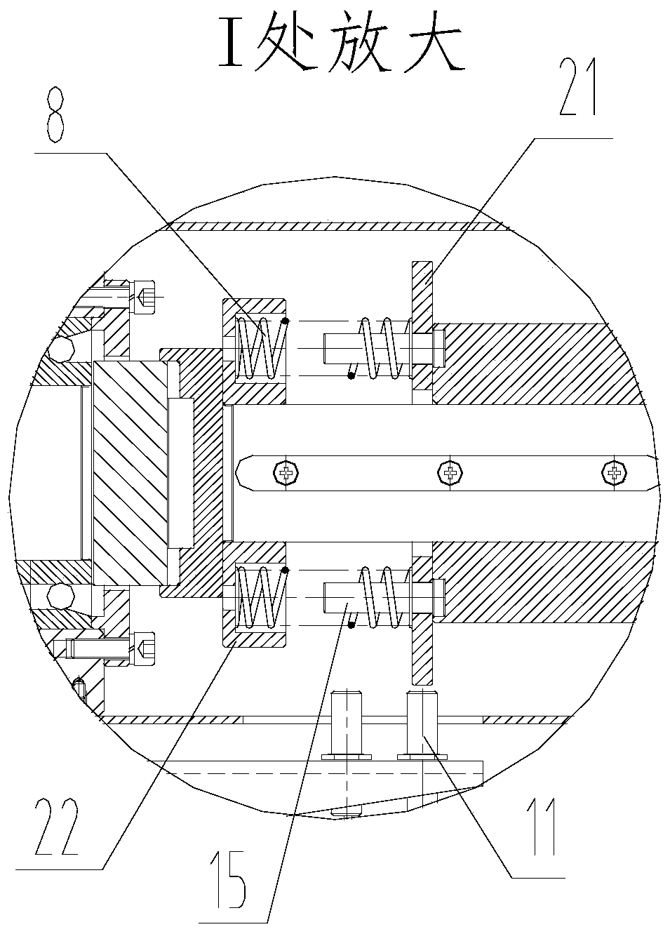
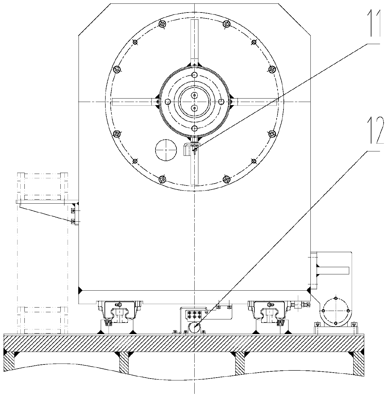
[0026] Such as Figure 1~4 Shown, the present invention comprises inertia flywheel 3, translation slide table 16, power transmission shaft 6, butt joint 9 and braking mechanism 18, wherein as Figure 4 As shown, the translation slide table 16 is driven by a hydraulic cylinder 13 to move along a linear guide rail 17, and the hydraulic cylinder 13 and the linear guide rail 17 are both installed on a base. Inertia flywheel 3 is installed on the described translation slide table 16, as figure 1 As shown, the two ends of the inertia flywheel 3 are provided with an inertia flywheel shaft 2, and each inertia flywheel shaft 2 is supported by a flywheel seat 4, and the flywheel seat 4 is installed on a translation slide 16, and the inertia flywheel 3 The inertia flywheel shaft 2 on the front side is connected with the transmission shaft 6 through a coupling 5, and t...


PUM


Abstract

The invention relates to the field of automobile gearbox detection, in particular to a gearbox no-load test inertia loading mechanism, including an inertia flywheel, a translation slide, a transmission shaft, a butt joint and a braking mechanism, wherein the inertia flywheel and the transmission shaft are installed On the translation slide table, inertia flywheel shafts are provided on both sides of the inertia flywheel, wherein the inertia flywheel shaft on the front side of the inertia flywheel is connected to the transmission shaft, and the end of the transmission shaft away from the inertia flywheel is connected to the The butt joint is connected, and the front end of the butt joint is provided with an application pin for docking with the gearbox to be tested, and the butt joint is driven to move by the translation slide table, and a buffer is provided between the transmission shaft and the butt joint The spring used, the inertia flywheel shaft on the rear side of the inertia flywheel is connected with the brake mechanism, and the inertia flywheel is controlled to start and stop by the brake mechanism. The present invention can apply external inertia to the gearbox under test according to the actual situation when the gearbox is subjected to no-load test.

Description

technical field [0001] The invention relates to the field of automobile gearbox detection, in particular to an inertia loading mechanism for a gearbox no-load test. Background technique [0002] The gearbox is one of the important components of the automobile transmission system, and also one of the most important components in the composition of the automobile. Due to the special importance of the gearbox, there are strict requirements for the performance testing of the gearbox after assembly. After the gearbox is assembled, it is necessary to carry out relevant no-load inspections without external torque. These inspections mainly include noise detection, shift performance detection, odometer sensor detection, reverse gear switch detection, and neutral gear switch detection. and other testing items to ensure the assembly quality of the gearbox. [0003] The traditional no-load detection work for the assembled gearbox usually only locates the gearbox on the detection mechan...

Claims


Application Information

Patent Timeline
Patent Type & Authority Patents(China)
IPC IPC(8): G01M13/02
Inventor 尹健白洪飞刘松凯郑德超
Owner SHENYANG INST OF AUTOMATION - CHINESE ACAD OF SCI
Why Eureka
Try Eureka