Wave velocity and thickness calibrating method for ultrasonic wave welding spot detection

A solder joint inspection and calibration method technology, applied in the direction of using ultrasonic/sonic/infrasonic, material analysis using sonic/ultrasonic/infrasonic, measurement of ultrasonic/sonic/infrasonic, etc., can solve the problem of increased production cost, low efficiency and waste of manpower and other problems, to achieve the effect of improving measurement accuracy, reliable measurement data, and reducing measurement errors.

Active Publication Date: 2014-10-22
HUNAN UNIV AISHENG AUTO TECH DEV
View PDF2 Cites 10 Cited by
  • Summary
  • Abstract
  • Description
  • Claims
  • Application Information

AI Technical Summary

Problems solved by technology

The basic principle of this type of equipment is to combine the incident and reflection characteristics of ultrasonic waves, and use piezoelectric crystals to generate ultrasonic longitudinal waves, which are incident vertically into the weld nugget. The acoustic impedance of the analyzed material must be slightly different, so the longitudinal wave velocity is also different, and there must be errors between the actual value and the theoretical value of the plate thickness, and manually adjusting the ultrasonic velocity and thickness is a waste of manpower, low efficiency, and indirectly leads to an increase in production costs.
[0003] There are many detection methods for ultrasonic solder joint detection. In the article "Principle Analysis of Wave Velocity and Probe Delay Calibration of Digital Ultrasonic Detector" written by Li Shengping of Qinghai Electric Power Scientific Experimental Research Institute, the method of calibrating the wave velocity of ultrasonic detector with test block is described. , the technical solution in this paper is to calibrate the wave velocity of the detector through a test block, but in the actual detection process, the wave velocity must have a big difference in the sheet metal parts of different materials. Obviously, the method pointed out in this paper cannot To meet the engineering needs, in addition, in the process of engineering practice, it is often necessary to calibrate the thickness of the workpiece, and the existing technology does not provide an effective method for checking the thickness of the workpiece

Method used


Image

  • Wave velocity and thickness calibrating method for ultrasonic wave welding spot detection
  • Wave velocity and thickness calibrating method for ultrasonic wave welding spot detection
  • Wave velocity and thickness calibrating method for ultrasonic wave welding spot detection

Examples


Embodiment Construction

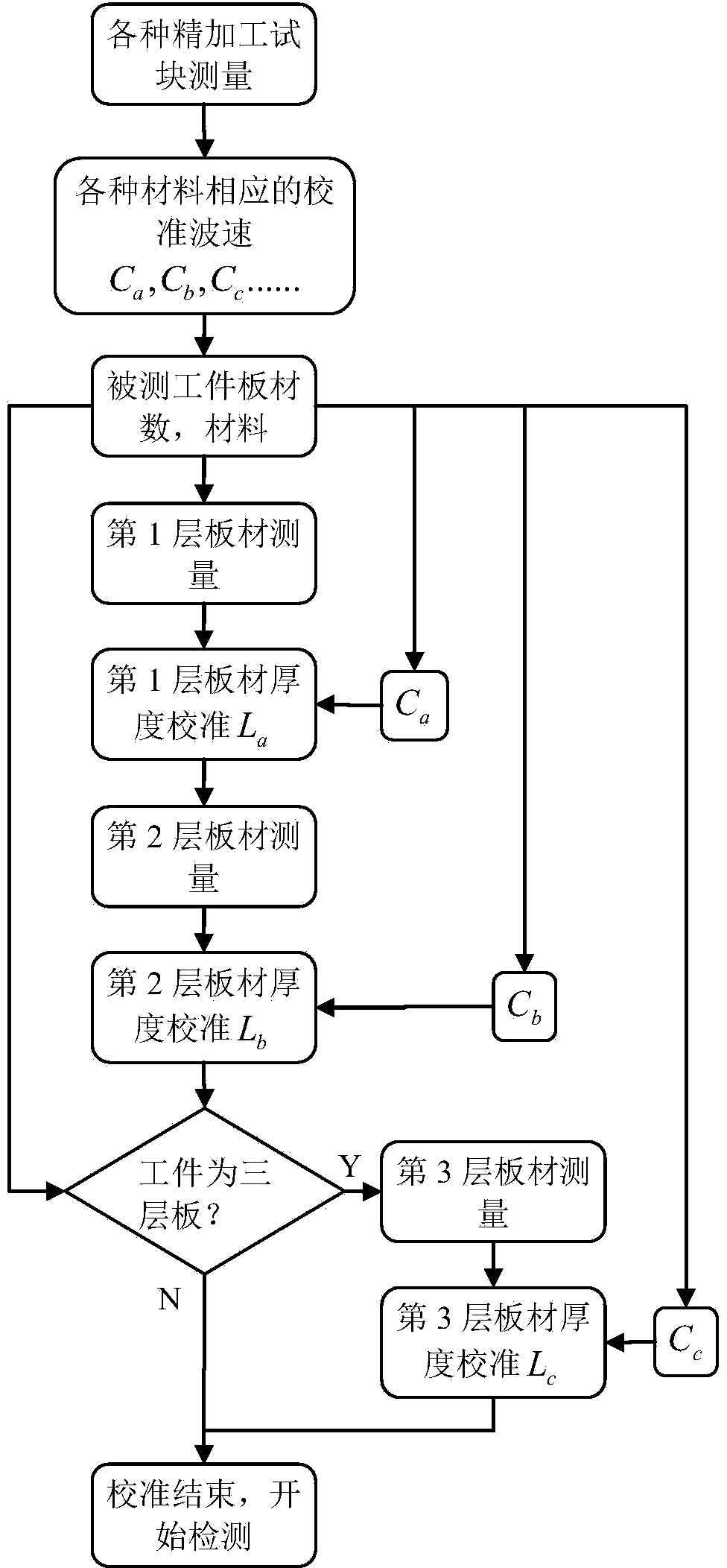
[0039] The following will be combined with Figure 1-3 Specific embodiments of the present invention will be described in detail.

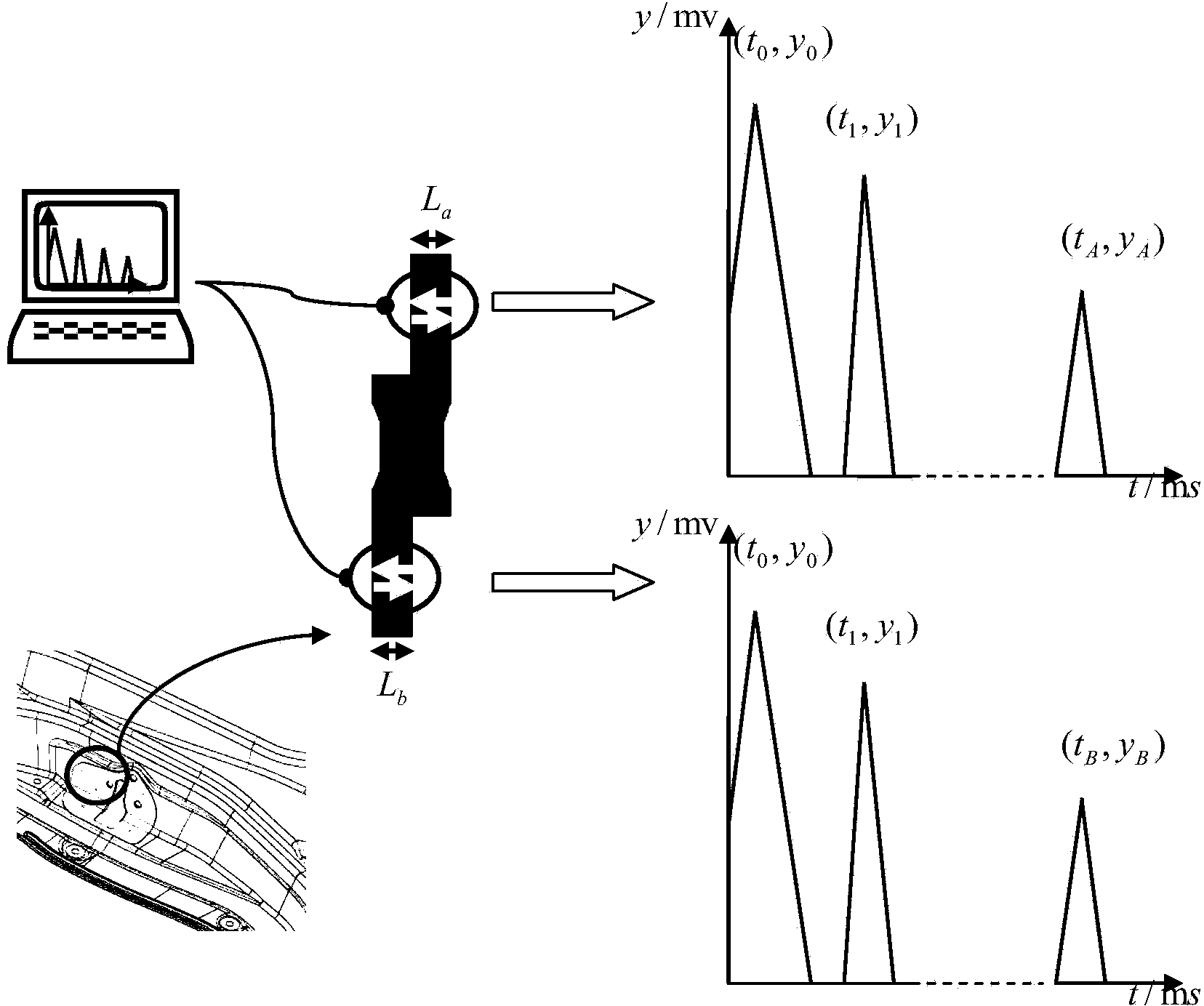
[0040] The method for calibrating the wave velocity and the thickness of the workpiece plate for ultrasonic solder joint detection according to the present invention first uses the finished test block to calibrate the wave velocity of different materials, and then uses ultrasonic equipment to measure several plates of the solder joint respectively, combined with the corresponding wave velocity , to calibrate the plate thickness. Such as figure 1 As shown, the specific flow of the calibration method of the present invention is as follows:

[0041] Step 1: Use the ultrasonic signal to measure the test block of the body-in-white material, and calculate the corrected wave velocity of the corresponding test block according to the measurement results;

[0042] In this step, the test blocks of the most commonly used materials for the body-in-white are...


PUM


Abstract

The invention relates to a wave velocity and thickness calibrating method for ultrasonic wave welding spot detection. A test block of a corresponding material is selected for to-be-tested workpieces of different materials, the wave velocity calibrating error caused by different materials is minimally reduced; meanwhile, the invention provides thickness calibration for the to-be-tested workpiece, and the defect of existing detection equipment is made up from the application point of view. By adopting the technical scheme provided by the invention, aiming at wave velocity calibration of different materials and thickness calibration of different workpieces, the measurement accuracy is greatly improved, the measurement error caused by inaccurate wave velocity and thickness is reduced, and thus the data measurement is more reliable.

Description

field of invention [0001] The invention relates to a welding quality monitoring method, in particular to a method for calibrating wave velocity and workpiece plate thickness for ultrasonic welding spot detection. Background technique [0002] At present, most of the car body sheet metal parts adopt spot welding structure. With the increasingly stringent quality requirements of the market, many manufacturers are looking for non-destructive spot welding inspection methods, so a large number of OEMs have begun to use ultrasonic welding spot inspection equipment. The basic principle of this type of equipment is to combine the incident and reflection characteristics of ultrasonic waves, and use piezoelectric crystals to generate ultrasonic longitudinal waves, which are incident vertically into the weld nugget. The acoustic impedance of the analyzed material must be slightly different, so the longitudinal wave velocity is also different, and there must be errors between the actual...

Claims


Application Information

Patent Timeline
Patent Type & Authority Applications(China)
IPC IPC(8): G01N29/30G01H5/00G01B17/02
Inventor 何清华邓江雪王国春曾琼
Owner HUNAN UNIV AISHENG AUTO TECH DEV
Why Eureka
Try Eureka