
Control method and system of holder camera device

A technology of a camera device and a control method, applied in the field of PTZ, can solve the problems of low correction accuracy, slow response, video captured by the camera device or insufficient image quality, etc., and achieve the effect of stabilization effect and fast correction speed.

Inactive Publication Date: 2016-06-15
TIANJIN YUANDU TECH CO LTD
View PDF5 Cites 48 Cited by
  • Summary
  • Abstract
  • Description
  • Claims
  • Application Information

AI Technical Summary

Problems solved by technology

The existing control method of the pan-tilt camera device has problems such as slow response in the correction process, low correction accuracy, etc., resulting in unqualified video or image quality captured by the camera device

Method used


Image

  • Control method and system of holder camera device
  • Control method and system of holder camera device
  • Control method and system of holder camera device

Examples


Embodiment 1

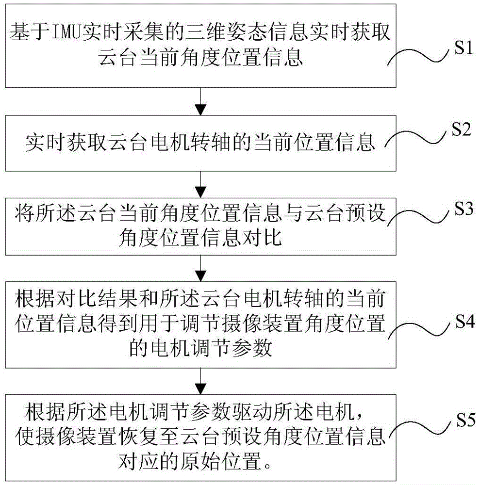
[0038] This embodiment discloses a control method of a pan-tilt camera device. Such as figure 1 As shown, the control method of the pan-tilt camera device in this embodiment includes the following steps:

[0039] Step S1: Obtain the current angular position information of the pan / tilt in real time based on the three-dimensional attitude information of the camera device collected in real time by an IMU (inertial measurement unit). Step S1 is divided into the following two steps, such as figure 2 Shown:

[0040] Step S101: The IMU (inertial measurement unit) collects the three-dimensional attitude information of the camera device in the earth coordinate system in real time through the gyroscope and the accelerometer.

[0041] Step S102: Perform Butterworth filtering and Kalman filtering on the 3D attitude information of the imaging device collected in real time by the IMU (inertial measurement unit) to obtain the current angular position information of the imaging device in ...

Embodiment 2

[0056] This embodiment discloses a control system of a pan-tilt camera device for realizing the control methods of various pan-tilt camera devices in preferred embodiment 1, the control system includes a pan-tilt current angle position information acquisition unit, a pan-tilt motor shaft A position information acquisition unit, a control unit and a motor drive unit.

[0057] Wherein, the current angular position information acquisition unit of the pan / tilt is used to obtain the current angular position information of the pan / tilt in real time and transmit it to the control unit. The current angular position information acquisition unit of the specific cloud platform includes an IMU (inertial measurement unit) and a signal processing unit. The unit is used to perform filtering processing and information conversion on the collected current angle position information of the camera device, and transmit the filtered signal to the control unit.

[0058] The position information acq...


PUM


Abstract

The invention discloses a control method and system of a holder camera device. The method and the system belong to the field of holder control methods and devices and are designed for solving such problems that methods and devices in the prior art are poor in stability augmentation effect. The method comprises the following steps: obtaining information of a current angle position of a holder by means of an inertia measurement unit; comparing the current angle position with a preset target angle position of the holder; acquiring information of a motor shaft position in real time to obtain a motor adjustment parameter; and using a motor to drive a camera device according to the motor adjustment parameter to return to an original position corresponding to the preset target angle position of the holder. The system is used to implement the method. The method and the system monitor position changes of the holder in real time, compare the current position with the preset position, obtain the motor adjustment parameter with the help of the current position of a motor, and drive the camera device to correct the position by means of the motor. The correction speed is high, and the stability augmentation effect is good.

Description

technical field [0001] The invention relates to the technical field of pan-tilts, in particular to a control method of a pan-tilt imaging device and a control system of the pan-tilt imaging device for realizing the method. Background technique [0002] The PTZ is the most common front-end monitoring device in the monitoring system. With the continuous development of monitoring technology, the monitoring quality requirements for monitoring products are getting higher and higher, that is, it is required that the pan / tilt can still obtain high-quality images in various complex application environments. [0003] A kind of pan-tilt monitoring mode is: during work, the pan-tilt will be affected by the application environment and other unstable situations will occur (such as the hand-held pan-tilt shakes with the hands), in order to ensure that the pan-tilt camera device can obtain stable high-definition video Or images, the camera needs to be corrected so that it is always at the...

Claims


Application Information

Patent Timeline
IPC IPC(8): G05D3/12
CPCG05D3/12
Inventor 詹先龙孙宇
Owner TIANJIN YUANDU TECH CO LTD
Learn More