
Electrical connector and production method thereof

A technology of electrical connectors and conductive terminals, which is applied in the field of electrical connectors and its production, can solve the problems of bending and deflection of grounding metal sheets, the inability to realize automatic production, and high production costs, so as to prevent accidents and realize automation Production and use are safe and reliable

Active Publication Date: 2018-05-29
DONGGUAN JINGHE ELECTRONICS TECH
View PDF6 Cites 0 Cited by
  • Summary
  • Abstract
  • Description
  • Claims
  • Application Information

AI Technical Summary

Problems solved by technology

[0004] However, in the above-mentioned method for producing the electrical connector at the USB Type-C socket end, on the one hand, the front ends of the conductive terminal groups of the formed upper and lower rows of conductive terminal blocks are exposed and suspended, so the upper and lower rows of conductive terminal blocks and the conductive terminal blocks When the third insulating seat is injection-molded on the grounding metal sheet, due to the extrusion of the injection fluid and other reasons, it is easy to cause the terminals of the upper and lower conductive terminal groups and the grounding metal sheet to bend and deflect, so that the terminals of the upper and lower conductive terminal groups are in contact with the grounding. Metal sheet contact, resulting in the formation of a short circuit in the process of use and the accident of burning, which is very unsafe to use; on the other hand, its production process is cumbersome and complicated, and automatic production cannot be realized, the production efficiency is low, and the yield rate is low, making the production cost high high

Method used


Image

  • Electrical connector and production method thereof
  • Electrical connector and production method thereof
  • Electrical connector and production method thereof

Examples


Embodiment Construction

[0034] In order to describe the technical content and structural features of the present invention in detail, the following further description will be made in conjunction with the embodiments and the accompanying drawings.

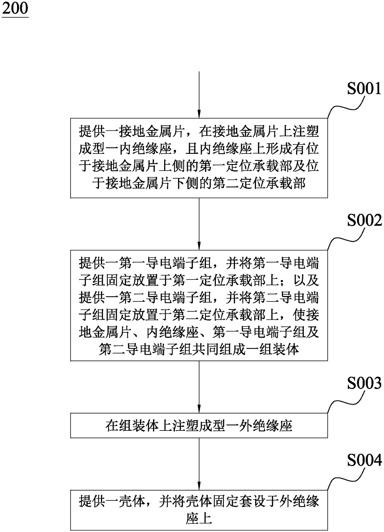
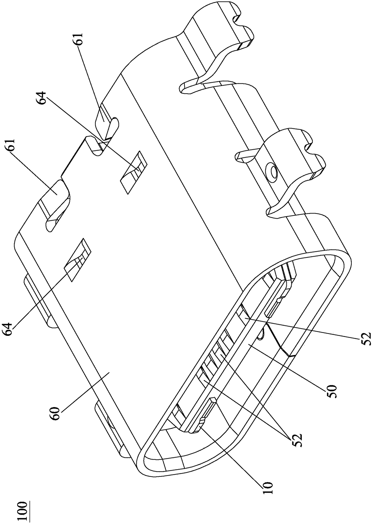
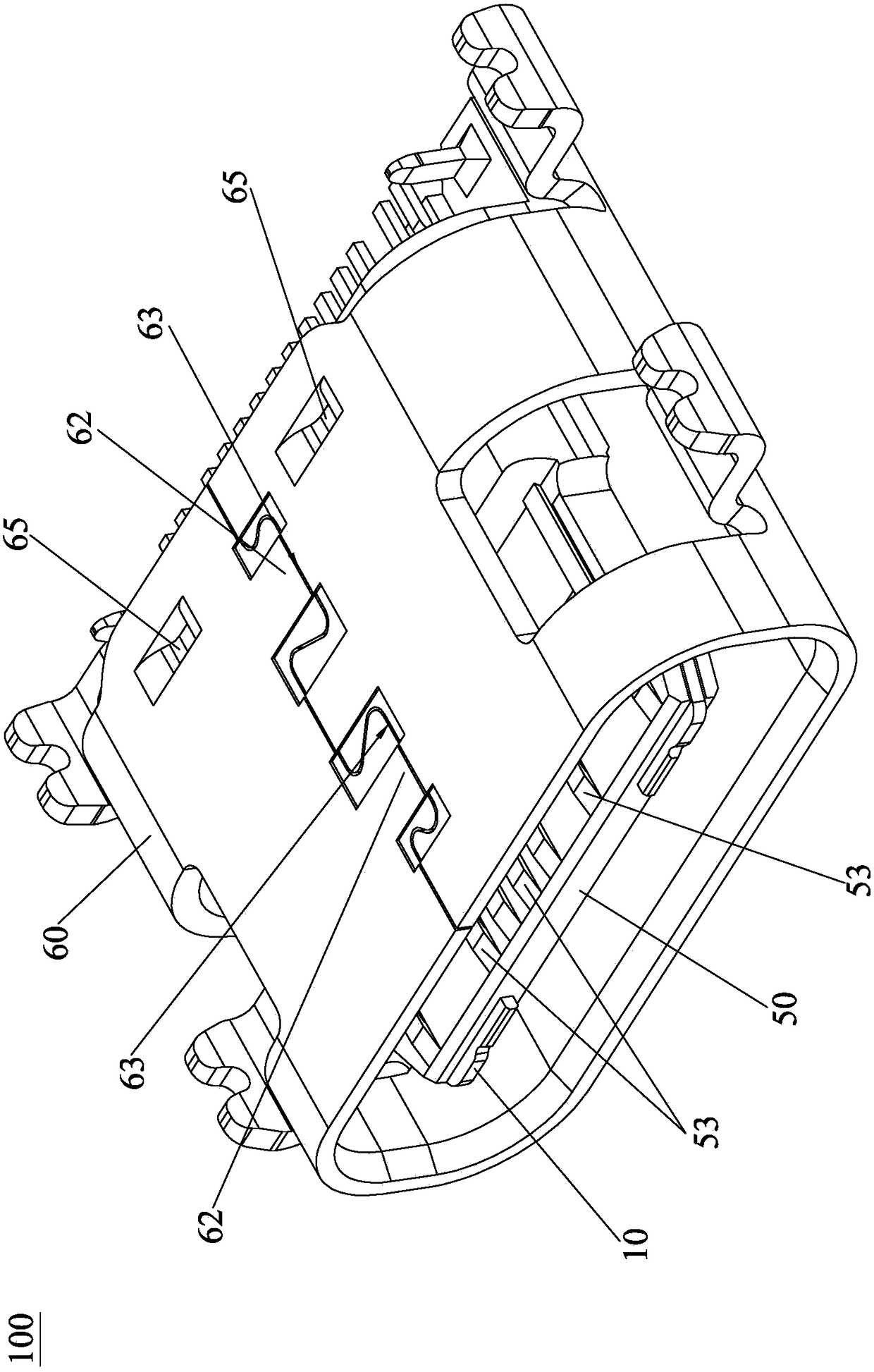
[0035] See Figure 2 to Figure 8 The electrical connector 100 of the present invention includes a grounded metal sheet 10, an inner insulating seat 20, an outer insulating seat 50, a first conductive terminal group 30, a second conductive terminal group 40, and a housing 60. The inner insulating seat 20 is injection molded (InsertMolding ) On the grounded metal sheet 10, that is, the grounded metal sheet 10 is embedded in the inner insulating seat 20. The inner insulating seat 20 is formed with a first positioning bearing portion (not marked in the figure) on the upper side of the grounded metal sheet 10 and On the second positioning bearing portion (not marked in the figure) on the lower side of the ground metal sheet 10, the first conductive terminal group ...


PUM


Abstract

The invention discloses a method for producing an electric connector. The method comprises the following steps of providing a grounding metal sheet; arranging an inner insulating base on the grounding metal sheet in an injection molding manner; forming a first positioning bearing part, positioned on the upper side of the grounding metal sheet, and forming a second positioning bearing part, positioned on the lower side of the grounding metal sheet, on the inner insulating base; providing a first conductive terminal group, enabling the first conductive terminal group to be fixedly placed on the first positioning bearing part; providing a second conductive terminal group, enabling the second conductive terminal group to be fixedly placed on the second positioning bearing part so as to enable the metal sheet, the inner insulating base, the first conductive terminal group and the second conductive terminal group to form an assembling body together; arranging an outer insulating base on the assembling body in an injection molding manner; and providing a shell, and enabling the shell to be fixedly arranged on the outer insulating base in a sleeving manner. Therefore, the contact between the first and second conductive terminal groups and the grounding metal sheet can be prevented, so that combustion accidents caused by short circuits in the use process can be avoided; and in addition, the method has simple production procedures and the production cost is lowered.

Description

Technical field [0001] The present invention relates to the technical field of electronic devices, in particular to an electrical connector and a production method thereof. Background technique [0002] With the rapid development of science and technology in the field of electronic devices, the volume of electronic products has increasingly developed along the trend of lightness, thinness and shortness, which also requires smaller and smaller components of electronic products. Among them, electrical connectors are particularly prominent. [0003] At present, the more commonly used production method for the electrical connector of the USB Type-C socket is to first perform injection molding (InsertMolding) the first and second insulating seats on the upper and lower rows of conductive terminal groups respectively to form the upper and lower rows of conductive terminals. The terminal block is then clamped between the upper and lower rows of conductive terminal blocks, and the third in...

Claims


Application Information

Patent Timeline
Patent Type & Authority Patents(China)
IPC IPC(8): H01R43/20H01R13/405H01R13/46H01R13/648
CPCH01R13/405H01R13/46H01R13/648H01R43/20
Inventor 沈海滨刘树涛任永红胡宜光
Owner DONGGUAN JINGHE ELECTRONICS TECH
Learn More