Switch cabinet with inner and outer cabinet bodies

A technology of switch cabinets and outer cabinets, which is applied in the field of switch cabinets, which can solve the problems of increasing the installation space of electrical components and the cabinet body is prone to moisture, and achieves the effect of increasing the installation space of electrical appliances

Inactive Publication Date: 2016-06-15
YANTAI POWER SUPPLY COMPANY OF STATE GRID SHANDONG ELECTRIC POWER +2
View PDF5 Cites 13 Cited by
  • Summary
  • Abstract
  • Description
  • Claims
  • Application Information

AI Technical Summary

Problems solved by technology

[0003] The purpose of the present invention is to provide a switchgear with an inner and outer two-layer cabinet structure, which can improve the problems existing in the prior art, realize ventilation by adopting a ventilation pipe structure, and avoid the problem that the inside of the cabinet is easily affected by moisture whe

Method used


Image

  • Switch cabinet with inner and outer cabinet bodies

Examples


Example Embodiment

[0018] Example 1:

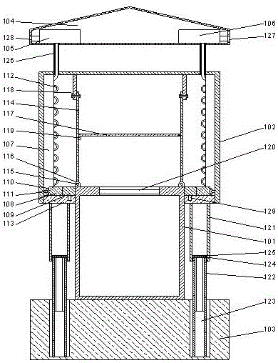
[0019] Such as figure 1 As shown, a switchgear with an inner and outer two-layer cabinet structure includes an inner cabinet 101 and an outer cabinet 102 arranged outside the inner cabinet. The inner cabinet and the outer Cabinet doors are respectively provided on the cabinet body, a top cover 104 is provided on the top of the outer cabinet body, a base 103 is provided at the bottom of the inner cabinet body, and the outer wall of the inner cabinet body and A cavity is formed between the inner walls of the outer cabinet, and a vent pipe 112 is provided in the cavity, and the vent pipe is clamped on the inner wall of the outer cabinet by a buckle. A vent hole is provided on the side end of the ventilation pipe facing the inner cabinet body, a bracket 126 is provided at the lower end of the top cover, the bracket is a hollow tubular structure, and the top cover is hollow. Structure, a fan 105 and a suction pump 106 are arranged inside the top cover, the input ...

Example Embodiment

[0023] Example 2:

[0024] In this embodiment, on the basis of Embodiment 1, preferably, the vertical mounting plates are two symmetrically arranged. Install the two vertical mounting plates in parallel on the top of the inner cabinet and under the top of the outer cabinet to facilitate the installation of electrical devices.

[0025] In order to facilitate the installation of electrical components, in this embodiment, a structure for horizontally fixing the electrical components is provided. Preferably, a horizontal mounting plate 117 is provided on one of the vertical mounting plates, and one end of the horizontal mounting plate is hinged to the vertical mounting plate. On the side wall of the vertical mounting board, a support bar 119 is provided on the other vertical mounting board, and the other end of the horizontal mounting board can be hung on the upper end surface of the support bar. When not needed, the horizontal mounting plate is attached to the vertical mounting plate...


PUM


Abstract

The invention discloses a switch cabinet with inner and outer cabinet bodies, which comprises an inner cabinet body and an outer cabinet body arranged outside the inner cabinet body, wherein both the inner cabinet body and the outer cabinet body are provided with cabinet doors; the top part of the outer cabinet body is provided with a top cover; the bottom part of the inner cabinet body is provided with a base; a cavity is formed between the outer wall of the inner cabinet body and the inner wall of the outer cabinet body; a vent pipe is arranged in the cavity; the vent pipe is clamped on the inner wall of the outer cabinet body via a buckle; the end surface of one side, facing the inner cabinet body, of the vent pipe is provided with a vent hole; and the lower end of the top cover is provide with a support. Ventilation is realized through adopting the vent pipe, the fact that the inner part of the cabinet body is likely to be affected with damp when a vent window structure is arranged is avoided, the cabinet body structure whose inner layer and the outer layer can be adjusted is adopted, the two layers of cabinet bodies can move relatively when needed, a structure with two vertical cabinet bodies is thus formed, and the space for mounting an electric appliance is increased.

Description

Technical field [0001] The invention relates to a switch cabinet with an inner and outer two-layer cabinet structure. Background technique [0002] The switch cabinet is mainly used to install electrical equipment for opening and closing, controlling and protecting electrical equipment. During the use of the switchgear, the operation of the electronic module will generate heat, which will cause the inside of the switchgear to heat up, especially in summer when it is prone to fire due to high temperature. Summary of the invention [0003] The purpose of the present invention is to provide a switch cabinet with an inner and outer cabinet structure, which can improve the problems existing in the prior art, realize ventilation by adopting a ventilation pipe structure, and avoid the problem that the inside of the cabinet is easily damp when the ventilation window structure is opened , At the same time, it adopts an adjustable cabinet structure with two layers inside and outside, which...

Claims


Application Information

Patent Timeline
IPC IPC(8): H02B1/56H02B1/30
CPCH02B1/30H02B1/565
Inventor 张静杨涛杨毅李虎徐颖王军波王秀平周毅胡国伟张婷婷田书然曲世凯董临江刘亭亭
Owner YANTAI POWER SUPPLY COMPANY OF STATE GRID SHANDONG ELECTRIC POWER
Why Eureka
Try Eureka