Electromagnetic coupling electricity-taking device and application thereof

A technology of power taking device and electromagnetic coupling, applied in induction heating, induction heating control and other directions, can solve the problems of inconvenience and cannot directly reflect the current size of power devices, etc., and achieve the effects of convenient production, reasonable structure and improved energy efficiency.

Inactive Publication Date: 2016-06-15
HANGZHOU SINODOD ELECTRIC
View PDF0 Cites 0 Cited by
  • Summary
  • Abstract
  • Description
  • Claims
  • Application Information

AI Technical Summary

Problems solved by technology

[0002] At present, the wire reel is an indispensable device for electromagnetic heating. Due to the wire loss of the wire reel and other reasons accompanied by heat generation, there is a certain distance between the control board and the heating body in the conventional design. Fans for radiators and other low-power auxiliary cooling devices All power needs to be taken from other control boards, which is extremely inconvenient
And the current sampling of the electromagnetic heating device is placed at the input of the mains, which cannot directly reflect the current of the power device

Method used


Image

  • Electromagnetic coupling electricity-taking device and application thereof
  • Electromagnetic coupling electricity-taking device and application thereof
  • Electromagnetic coupling electricity-taking device and application thereof

Examples


Embodiment 1

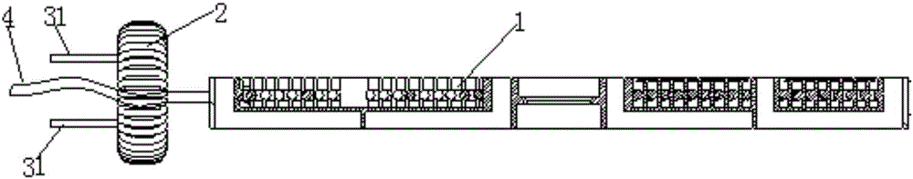
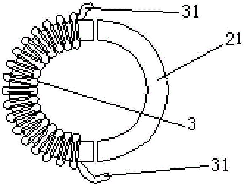
[0013] Embodiment 1: refer to Figure 1-3 . An electromagnetic coupling power-taking device, comprising a plurality of high-frequency current wires 4 and a ring core 2, coils 3 are wound around the rings of the ring core 2, and each high-frequency current wire 4 passes through a single or multiple The central hole of the annular core 2, and the two ends of the coil 3 are drawn out as two electrodes 31 of the coupling power supply. The annular core 2 is circular, or formed by combining two semicircular magnetic cores 21 , or combining arc-shaped magnetic cores. The ring core 2 includes a magnetic ring core and a non-magnetic ring core. The positions of the coils 3 on the annular core 2 are not fixed, as long as they are wound on the annular core 2 . The coil 3 is wound on the annular core 2, and the high-frequency current wire 4 passes through the annular core 2. The high-frequency high-frequency current generates a high-frequency magnetic field, and the coil coupling can ge...

Embodiment 2

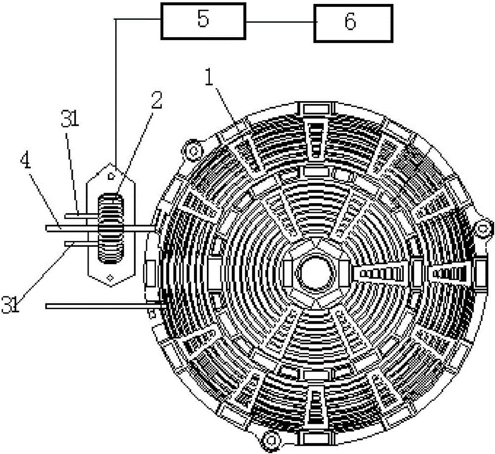
[0014] Embodiment 2: refer to Figure 1-3 . On the basis of Embodiment 1, a kind of electromagnetic coupling power-taking device for electromagnetic oven implementing claim 1 is provided, wherein the high-frequency current wire 4 is the power lead of the induction cooker reel, the wire in the reel of the induction cooker or the resonant part of the circuit board of the induction cooker One or more of the wires, the power leads of the induction cooker reel, the wires in the induction cooker reel and the wires at the resonance of the induction cooker circuit board respectively pass through the central hole of a single or multiple ring cores 2, and each ring core Lead wires at both ends of the coil 3 wound on the body 2 serve as two electrodes 31 of the coupling power supply respectively. The electromagnetic coupling power-taking device of the electromagnetic cooker also includes a radiator 6 and a control circuit 5. The control circuit 5 collects current signals from each coupl...


PUM


Abstract

The invention relates to an electromagnetic coupling power-taking device and its application. It passes a high-frequency current line through the center of a ring-shaped core body with a coil, and the two ends of the coil lead out two electrodes as a coupling power supply to form a potential difference and Generate power, which can be applied to electric appliances such as induction cooker and electric ceramic cooker as auxiliary power supply.

Description

technical field [0001] The invention relates to an electromagnetic coupling power-taking device and its application. Background technique [0002] At present, the wire reel is an indispensable device for electromagnetic heating. Due to the wire loss of the wire reel and other reasons accompanied by heat generation, there is a certain distance between the control board and the heating body in the conventional design. Fans for radiators and other low-power auxiliary cooling devices All power needs to be taken from other control boards, which is extremely inconvenient. Moreover, the current sampling of the electromagnetic heating device is placed at the input of the mains, which cannot directly reflect the current of the power device. Contents of the invention [0003] The purpose of the present invention is to solve the problems in the background technology, to provide an electromagnetic coupling power-taking device and its application, which passes through the center of th...

Claims


Application Information

Patent Timeline
Patent Type & Authority Applications(China)
IPC IPC(8): H05B6/06
CPCH05B6/06
Inventor 高新忠甘嵩冯祥远冯子琪徐锋平
Owner HANGZHOU SINODOD ELECTRIC
Why Eureka
Try Eureka