Energy-saving hydraulic hybrid power system of loader

A technology of hybrid power system and loader, applied in the field of power system, can solve the problems of reduced operating efficiency, reduced transmission efficiency of hydraulic torque converter, waste, etc.

Active Publication Date: 2013-01-02
JIANGSU XCMG CONSTR MASCH RES INST LTD
View PDF0 Cites 3 Cited by
  • Summary
  • Abstract
  • Description
  • Claims
  • Application Information

AI Technical Summary

Problems solved by technology

There are frequent start-stop and reciprocating movements during the operation of the loader. Due to the heavy weight of the whole machine, a large amount of energy will be released when decelerating and braking. This part of energy is usually consumed on the valve port of the hydraulic valve, which not only wastes energy, but also Can cause heat generation in the system and decrease in component life
The transmission efficiency of the hydraulic transmission is low, especially when encountering heavy loads, the transmission efficiency of the hydraulic torque converter drops sharply, which reduces the operating efficiency and causes a waste of energy
At present, the braking kinetic energy of the loader is converted into heat energy by the brake device and is wasted; for the problem of low efficiency of the torque converter, the existing energy-saving loaders usually use methods such as double pump wheels, double guide wheels, double turbines and transmissions. Improve the transmission efficiency, but the above method fails to fundamentally solve the problem of low transmission efficiency under heavy load, and the failure rate is high
[0003] The power system of the existing loader generally has problems such as high fuel consumption, high emission, low system efficiency during heavy loads, and general waste of braking kinetic energy.

Method used


Image

  • Energy-saving hydraulic hybrid power system of loader

Examples


Embodiment 1

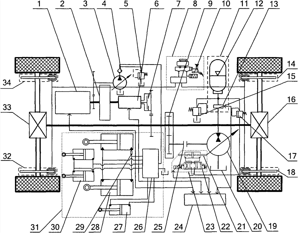
[0020]Embodiment 1: The hybrid system includes an engine 1, a hydraulic torque converter 2, a hydraulic variable pump 3, a one-way valve 4, a second overflow valve 5, a transmission 6, a wet clutch 7, and a mechanical friction brake controller 8 , torque coupler 9, internal displacement sensor 10, high-pressure hydraulic energy storage assembly 11, high-pressure hydraulic accumulator 12, two-position two-way reversing valve 13, first rear axle mechanical friction brake 14, first overflow valve 15, Rear axle 16, pressure reducing valve 17, second rear axle mechanical friction brake 18, hydraulic pump / motor 19, oil tank 20, variable cylinder 21, electro-hydraulic servo valve 22, hydraulic pump / motor control unit 23, central controller 24, Electromagnetic clutch 25, distribution valve 26, steering cylinder 27, boom cylinder 28, pressure sensor 29 of excavation mechanism, bucket cylinder 30, hydraulic actuator 31, second front axle mechanical friction brake 32, front axle 33 and fi...


PUM


Abstract

The invention relates to an energy-saving hydraulic hybrid power system of a loader and belongs to a power system of the loader. An engine of the hybrid power system is in mechanical connection with a hydraulic variable pump and a hydraulic torque converter; an oil outlet of the hydraulic variable pump is communicated with an oil inlet of a one-way valve; an oil inlet of a second overflow valve and a distribution valve are communicated with oil inlets or oil return ports of the one-way valve, an oil tank, a movable arm oil cylinder, a bucket oil cylinder and a steering oil cylinder respectively; an oil inlet of a hydraulic pump / motor control component is communicated with an oil outlet of a reducing valve; each oil return port is communicated with the oil tank; an oil outlet of a two-position two-way reversing valve is communicated with an oil inlet of the hydraulic pump / motor; the hydraulic pump / motor component and the hydraulic pump / motor are in mechanical connection; and an output shaft of the hydraulic pump / motor is in mechanical connection with the input ends of a front axle and a rear axle through an electromagnetic clutch and a torque coupler. The energy-saving hydraulic hybrid power system has the advantages that: the hydraulic hybrid power system can reclaim the braking kinetic energy of the whole machine, improves the working efficiency and working performance of thewhole machine and has long service life.

Description

technical field [0001] The invention relates to a power system of a loader, in particular to an energy-saving hydraulic hybrid power system of the loader. Background technique [0002] The loader not only needs to travel but also to perform loading operations. Part of the power of the engine drives the traveling mechanism through the hydraulic torque converter and gearbox, and the other part drives the hydraulic cylinder through the hydraulic oil pump to realize steering and loading. There are frequent start-stop and reciprocating movements during the operation of the loader. Due to the heavy weight of the whole machine, a large amount of energy will be released when decelerating and braking. This part of energy is usually consumed on the valve port of the hydraulic valve, which not only wastes energy, but also It will cause heat generation in the system and a reduction in component life. The transmission efficiency of the hydraulic transmission is low, especially when enco...

Claims


Application Information

Patent Timeline
Patent Type & Authority Patents(China)
IPC IPC(8): B60K6/12
CPCY02T10/6208Y02T10/62
Inventor 孙辉罗衍领景军清曹文东
Owner JIANGSU XCMG CONSTR MASCH RES INST LTD
Why Eureka
Try Eureka