Tissue compression device with multi-chamber bladder

A capsule and chamber technology, used in pneumatic massage, massage aids, passive exercise equipment, etc.

Active Publication Date: 2016-06-15
MEDTRONIC VASCULAR INC
View PDF9 Cites 3 Cited by
  • Summary
  • Abstract
  • Description
  • Claims
  • Application Information

AI Technical Summary

Problems solved by technology

Arterial blood flow is pulsatile in nature and can be challenging for any physician seeking to achieve hemostasis at the arterial entrance

Method used


Image

  • Tissue compression device with multi-chamber bladder
  • Tissue compression device with multi-chamber bladder
  • Tissue compression device with multi-chamber bladder

Examples


Embodiment Construction

[0071] In the following description of illustrative embodiments, reference is made to the accompanying drawings which form a part hereof, and in which are shown by way of illustration specific embodiments. It is to be understood that other embodiments may be utilized and structural changes may be made without departing from the scope of the present invention.

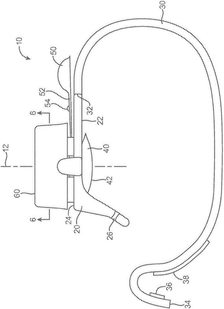
[0072] exist figure 1 A side view of an illustrative embodiment of the tissue compression device 10 described herein is depicted in . The tissue depressing device 10 includes a base 20 and a retaining structure 30 attached to the base 20 . In the depicted embodiment, the retention structure 30 is in the shape of a strip, which may be configured to wrap around a limb, such as an arm, on or in which the tissue to be compressed by the tissue compression device 10 is located. As described herein, in one or more embodiments, the tissue depressing devices described herein can be configured to depress the portal into the rad...


PUM


Abstract

Tissue compression devices including a multi-chamber bladder that is retained within the tissue compression device, with the multi-chamber bladder being positioned in a bladder orifice in a base of a compression device body. The multi-chamber bladder includes at least one upper chamber located above the base and at least one lower chamber located below the base. The lower chamber is located between the base and a selected location on a patient when the compression device is positioned over selected tissue such as, e.g., a radial artery, as described herein.

Description

[0001] related application [0002] This application claims under 35 U.S.C §119 U.S. Provisional Application No. 61 / 895,940, entitled "Tissue Compression Device With Multichamber Balloon"; U.S. Provisional Application No. 61 / 895,953, entitled "Tissue Compression Device With Tissue Compression Device”; and U.S. Provisional Application No. 61 / 895,944, entitled “Tissue Compression Device With Tension Limiting Band Retainer”—all of which were filed on October 25, 2013 and are hereby incorporated by reference . [0003] Tissue compression devices having multi-chambered balloons and methods of using the same are described herein. Background technique [0004] Diagnosis and treatment of coronary artery disease is now routinely accomplished using vascular delivery devices and technologies. Vascular delivery can provide several benefits because access to a desired location within a patient's body can be obtained without the need for general anesthesia or more invasive surgical techni...

Claims


Application Information

Patent Timeline
Patent Type & Authority Applications(China)
IPC IPC(8): A61B17/135A61F5/34
CPCA61B17/132A61B2017/00243A61B2017/00778A61F5/32A61B17/135A61B2017/12004A61H1/006A61H9/0092A61B17/12A61B17/1325
Inventor S·萨特奇M·霍夫C·弗兰纳瑞R·O·L·皮尔伦Y·米亚西塔B·J·梅森J·伯格伦德
Owner MEDTRONIC VASCULAR INC
Why Eureka
Try Eureka