Magnetically sealed double-body vacuum cup

A thermos cup and magnetic sealing technology, applied in the field of thermos cups, can solve the problems of difficulty in manufacturing, obstructing the taking of cups, complicated switch structure, etc., and achieve the effects of maintaining integrity, reliable function and novel principle.

Inactive Publication Date: 2016-06-22
CHENGDU UNIVERSITY OF TECHNOLOGY
View PDF4 Cites 4 Cited by
  • Summary
  • Abstract
  • Description
  • Claims
  • Application Information

AI Technical Summary

Problems solved by technology

[0002] Thermos cups are common daily necessities in people's lives. Its function is to keep hot water warm, but it often causes the inconvenience that the water temperature will be too high when drinking water is needed. In order to solve this problem, some solutions have emerged
[0003] For example, the Chinese patent "insulation cup capable of rapidly changing temperature" with the publication number CN202801040U and the Chinese patent "multipurpose insulation cup" with the publication number 103584639A can realize rapid cooling, but the first method can only cool the whole glass of water
The second way, although partial cooling can be achieved, but every time you drink water, you have to unscrew the lid and the cold water cup at the same time, which is inconvenient to use and the opening of the cooling cup affects the heat preservation
However, the disadvantages of this method of setting the channel switch on the side wall of the bottle body are: 1. The switch is arranged on the side wall of the bottle body, which destroys the integrity of the bottle body as a container, resulting in difficulties in manufacturing, and the switch is located in a water area. It is easy to cause water seepage and has high sealing requirements for switches
2. When using the switch, the hand must be placed in an operable position, which is very inconvenient to use
4. The body of the cup is usually taken by hand, and the switch is set on the side wall to prevent the hand from taking the cup, causing inconvenience
But its switch structure is complicated, and the method of setting the button outside the cup body increases the difficulty of sealing and the corresponding structure, and the water switch must be pressed every time it is used

Method used


Image

  • Magnetically sealed double-body vacuum cup
  • Magnetically sealed double-body vacuum cup
  • Magnetically sealed double-body vacuum cup

Examples


Embodiment 1

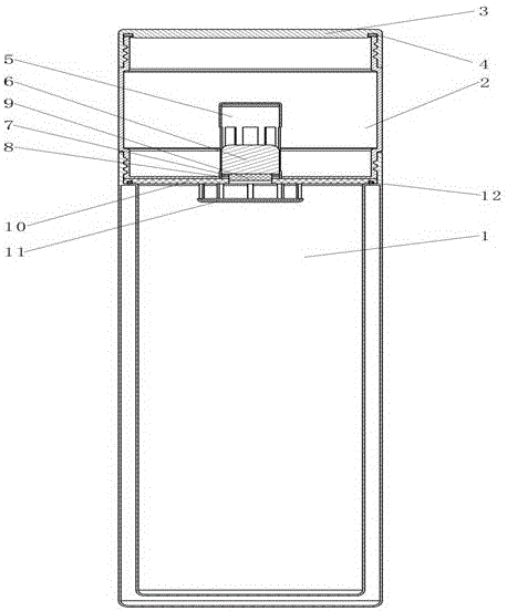
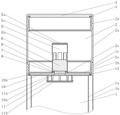
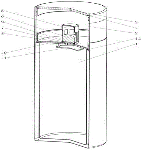
[0041] Example one, such as Figure 1 to Figure 5 As shown, the lower cup 1 is composed of an inner insulating layer 1a, an outer insulating layer 1b, and a lower cup mouth 1c. The lower cup mouth 1c is provided with internal threads.

[0042] The upper cup 2 is composed of an upper cup body 2a, an upper cup bottom 2b, a bottom hole 2c, and a heat insulation board 10. The cup opening of the upper cup body 2a and the lower end of the upper cup body 2a are respectively provided with a cup opening external thread 2d and a lower end external thread 2e, and the cup bottom hole 2c is located in the center of the upper cup bottom 2b. The lower external thread 2e of the upper cup body 2a and the internal thread of the lower cup opening 1c form a threaded connection. The heat insulation board 10 is placed at the bottom of the upper cup body 2a, and its center has a heat insulation board through hole 10a smaller than the bottom hole 2c of the cup. The outer end of the heat insulation boar...

Embodiment 2

[0047] Example two, such as Figure 6 to Figure 9 As shown, different guides 5 are used. The guide device 5 can be composed of a guide ring 5e and a guide ring connecting strip 5d. The guide ring 5e is a circular ring member, and the outer edge of the guide ring 5e is distributed with notches corresponding to the anti-rush cover connecting strip 11a, so that the guide ring 5e can slide along the anti-rush cover connecting strip 11a. There are 10 guide ring connecting strips 5d, one end is distributed and connected to the inner edge of the guide ring 5e. The guide ring 5e is connected to the heat insulation layer 9 through the guide ring connecting strip 5d. The guide ring 5e also limits the drop of the weight 6.

Embodiment 3

[0048] Example three, such as Figure 10 to Figure 12 As shown, there is another guiding device 5. The guide device 5 is composed of a guide ring 5h, a connecting rib 5i, a guide hole 11c, a guide rod 5f, and a limit cap 5g. The guide ring 5h is an annular piece, which is connected to the inner side of the through hole 10a of the heat insulation board through four connecting ribs 5i. The guide hole 11c is a through hole opened in the center of the anti-rush cover 11, the limit cap 5g is connected to the lower end of the guide rod 5f in a disc shape, and the upper end of the limit rod 5f passes through the guide hole 11c and the guide ring 5h to connect with the heat insulation layer 9. . The limit cap 5g has a limit effect on the drop of the heavy hammer 6.

[0049] The working process of the embodiment is:

[0050] Unscrew the upper cup 2, inject hot water into the lower cup 1, and then tighten the upper cup 2. Due to the heat insulation effect of the heat insulation board 10 ...


PUM


Abstract

The invention discloses a magnetically sealed double-body thermos cup. There is a central hole at the bottom of the upper cup, and a heat insulation plate is placed at the bottom of the upper cup body. There is a through hole in the center that is smaller than the bottom hole of the cup. The weight is a cylindrical magnetic conductive metal. pieces. The suction part is formed by a magnetic ring and a weight. The magnetic ring is a magnetic ring whose inner diameter is the same as that of the through hole of the heat shield, and is connected to the center of the heat shield. The magnetic adjustment pad is connected under the weight, and there is a heat insulation layer under the weight. The guide device is composed of a cap and a column, which guide and limit the movement of the weight. The lower end of the column is connected to the periphery of the bottom hole of the upper cup, and the upper end is connected to the cap. The cap acts as a limit to the falling of the weight, buffering Pad cushions the impact of the weight on the guide. The impact shield is located below the through hole in the heat shield. The thermos cup is turned upside down, the weight falls to make hot water flow into the upper cup, the thermos cup is placed upright, the weight falls, and under the action of the magnetic force, the weight presses the magnetic adjustment pad to seal the water. The invention has novel principle, simple structure and convenient use.

Description

Technical field [0001] The invention relates to a daily necessities, in particular to a thermos cup which can quickly cool part of hot water with a magnetic material sealing a water passage. Background technique [0002] The thermos cup is a common daily product in people's lives. Its function is to keep the hot water at the temperature, but it often causes the inconvenience that the water temperature is too high when drinking water. To solve this problem, some solutions have appeared. [0003] For example, the Chinese patent "Insulation Cup capable of rapid temperature change" with publication number CN202801040U and the Chinese patent "Multi-purpose Insulation Cup" with publication number 103584639A can achieve rapid cooling, but the first method can only cool the whole cup of water. In the second method, although partial cooling can be achieved, the lid and cold water cup must be unscrewed at the same time each time you drink water, which is inconvenient to use and the opening o...

Claims


Application Information

Patent Timeline
Patent Type & Authority Applications(China)
IPC IPC(8): A47G19/22A47J41/00
CPCA47G19/2205A47J41/00
Inventor 杨勇杨影
Owner CHENGDU UNIVERSITY OF TECHNOLOGY
Why Eureka
Try Eureka