
Method for controlling tail wiggling quantity of inclined rolling perforator

A technology of cross-rolling piercing and tail swing, applied in the direction of tail end control, rolling mill control device, metal rolling, etc., can solve the problems of excessive capillary ellipse, safety accidents, aggravating the deviation of the tube billet from the rolling line, etc. The effect of improving quality and avoiding safety accidents

Inactive Publication Date: 2016-06-22
XI'AN UNIVERSITY OF ARCHITECTURE AND TECHNOLOGY
View PDF8 Cites 11 Cited by
  • Summary
  • Abstract
  • Description
  • Claims
  • Application Information

AI Technical Summary

Problems solved by technology

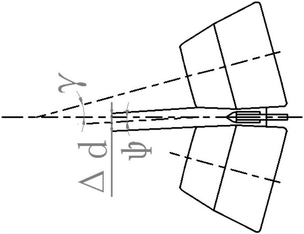
This kind of swing will further exacerbate the deviation of the tube billet from the rolling line, resulting in quality defects such as excessive ovality and uneven wall thickness of the capillary tube, and safety accidents may occur when the swing range is too large

Method used


Image

  • Method for controlling tail wiggling quantity of inclined rolling perforator
  • Method for controlling tail wiggling quantity of inclined rolling perforator
  • Method for controlling tail wiggling quantity of inclined rolling perforator

Examples


Embodiment 1

[0087] Taking a φ240mm two-roll skew rolling mill as an example, the billet is a φ50mm round steel, which is rolled into a φ50mm capillary tube.

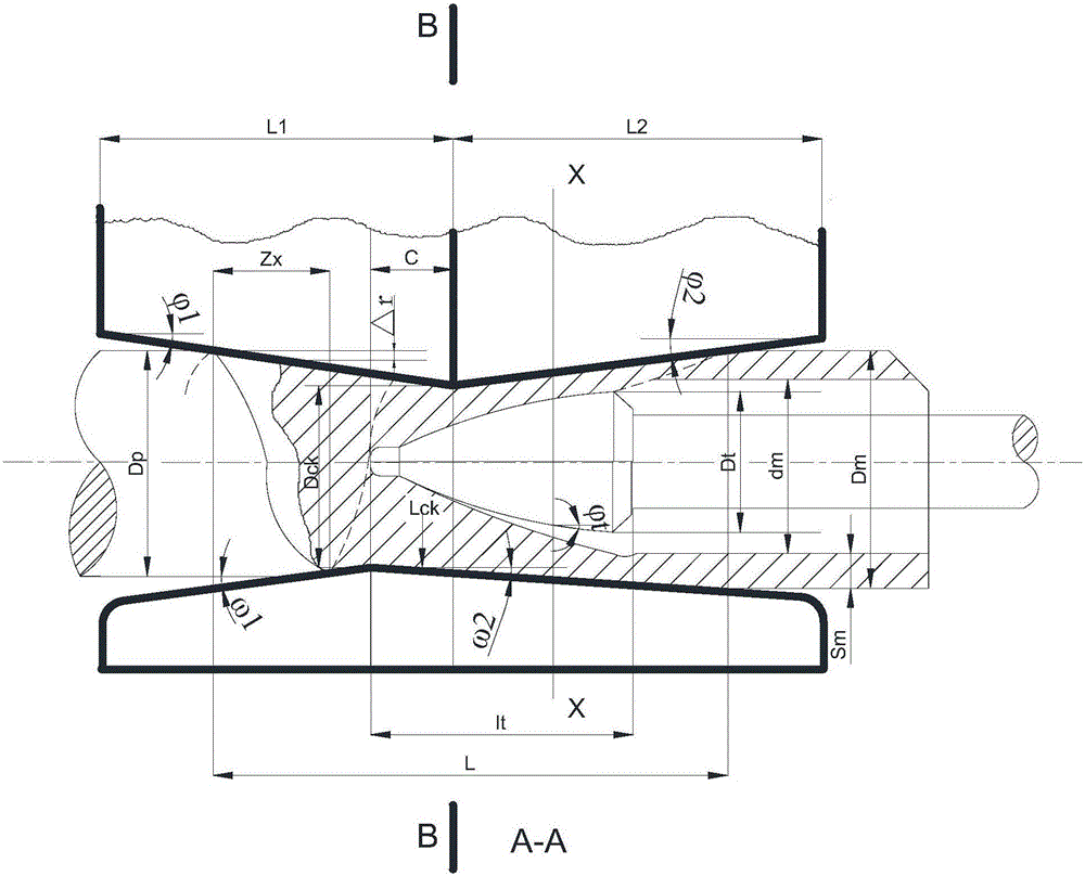
[0088] Known: D 0 =240mm, L 1 =74.44mm, L 2 =62.00mm, β=15°, γ=15°, D ck0 =43.5mm, L ck0 =51.6mm, L ck1,2 =58.6mm, Z x =18mm, ω 1 = 2°, ω 2 =1.6°, l=2000mm.

[0089] Select five positions, with the center line of rolling as the origin, respectively L 1 =50.8mm, 28.6mm, 0, L 2 = 30mm, 50mm.

[0090] Measure the distance between the rolls D ck They are 47.94mm, 46.00mm, 43.5mm, 46.12mm, 47.87mm respectively.

[0091] Measure the guide plate distance L ck They are 55.19mm, 53.62mm, 51.6mm, 53.24mm, 54.33mm respectively.

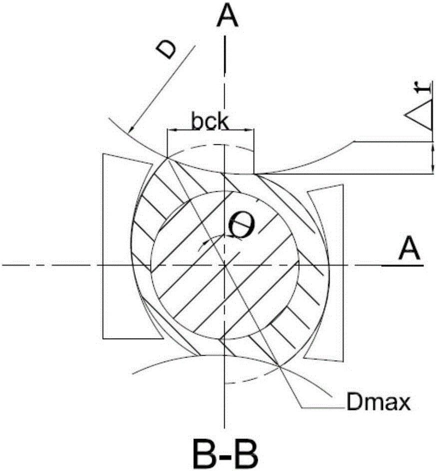
[0092] The calculated ellipticity coefficients ξ are 1.15, 1.17, 1.19, 1.15, 1.13, respectively.

[0093] The ellipticity coefficient ξ≥1.12 of the billet at the entrance of the roll, so the billet is biased to one side of the roll, and the offset of the billet at a certain point during the rolling pr...

Embodiment 2

[0100] Taking the φ100mm barrel roll of a certain factory as an example, it is rolled into a φ80*7mm capillary tube;

[0101] Known: D 0 =550mm, D p = 100mm, D m =80mmL 1 = L 2 =81.7mm, β=8°, γ=0°, D ck0 =90mm, L ck0 =99mm, L ck1,2 =121mm, Z x =19mm, l 1 = l 2=180mm, ω 1 = ω 2 =3.5°, l=2000mm.

[0102] Select five positions, with the center line of rolling as the origin, respectively L 1 =70mm,44.3mm,0,L 2 = 30mm, 70mm.

[0103] Measure the distance between the rolls D ck They are 98.56mm, 95.42mm, 90mm, 93.67mm, 98.56mm respectively.

[0104] Measure the guide plate distance L ck They are 107.56mm, 104.42mm, 99mm, 102.67mm, 107.56mm respectively.

[0105] The calculated ellipticity coefficients ξ are 1.09, 1.09, 1.1, 1.1, 1.09 respectively.

[0106] The ellipticity coefficient ξ of the blank at the entrance of the roll is x ·tan ω 1 , the corrected tail wagging amount d x =k·Δd=k·l x ·tan ω 1 , at a distance l from the roll hole throat x Three sets o...


PUM


Abstract

The invention discloses a method for controlling a tail wiggling quantity of an inclined rolling perforator. The method comprises the steps of: 1) measuring parameters of the inclined rolling perforator and a blank; 2) judging the deviation of the blank in the rolling process; 3) calculating a deviation quantity delta d of the tail part of the blank in one place in the rolling process; 4) correcting the tail wiggling quantity of the blank to obtain a corrected tail wiggling quantity dx; and 5) controlling of the tail wiggling quantity of the blank: control devices for preventing the blank from swinging are mounted on the left and right sides of the blank in an inlet of the inclined rolling perforator far from the center line dx of the blank. Aiming at the tail wigging problem of the pipe blank caused by a complex deformation area with an asymmetric shape in a traditional inclined rolling perforating process, the method obtains the tail wigging quantity of the pipe blank through theoretical analysis; and according to the magnitude of the wigging quantity, multiple control devices are mounted in the inlet of the inclined rolling perforator to achieve the purpose of controlling the tail wiggling of the pipe blank, so that the quality of perforated pipe is improved, and the generation of unnecessary accidents in actual production is prevented.

Description

technical field [0001] The invention belongs to the field of seamless steel pipe production in the metallurgical industry, and relates to a method for controlling the amount of tail swing of a pipe blank in the process of skew rolling and piercing. Background technique [0002] At present, in the cross-rolling piercing process, because the piercing deformation zone has a complex spatial geometry, it is surrounded by deformation tools such as rolls, guide plates, and plugs. The cross-section is from the entrance end where the tube billet is in contact with the roll to the exit end away from the roll, gradually transitioning from a solid circle to a hollow ring, and the longitudinal section is formed by inserting an arc-shaped top between two cones with small bottoms connected. During the spiral advancement of the tube billet along the rolling line, it will deviate from the rolling line (the center line surrounded by the spiral advance of the tube billet) and approach the roll...

Claims


Application Information

Patent Timeline
Patent Type & Authority Applications(China)
IPC IPC(8): B21B37/78B21B37/72B21B19/04
CPCB21B19/04B21B37/72B21B37/78
Inventor 庞玉华于亮庄博米娇娇廖毅
Owner XI'AN UNIVERSITY OF ARCHITECTURE AND TECHNOLOGY
Learn More