Eureka AIR delivers breakthrough ideas for toughest innovation challenges, trusted by R&D personnel around the world.

Electric circular saw cutting control device

A technology for control devices and electric circular saws, which is applied in the direction of sawing machine devices, circular saws, sawing equipment, etc., and can solve problems such as poor visibility and inability to realize vertical linear motion

Active Publication Date: 2016-06-22
POSITEC POWER TOOLS (SUZHOU) CO LTD
View PDF6 Cites 3 Cited by
  • Summary
  • Abstract
  • Description
  • Claims
  • Application Information

AI Technical Summary

Problems solved by technology

[0003] Generally, the slide rail part of the electric circular saw realizes the downward cutting action of the saw blade through the movement of the bearing in the arc groove. During the cutting process of the saw blade, the trajectory is arc, and the vertical linear motion cannot be realized; the visibility is poor. Difference

Method used


Image

  • Electric circular saw cutting control device
  • Electric circular saw cutting control device
  • Electric circular saw cutting control device

Examples


Embodiment Construction

[0036] In order to further illustrate the technical means adopted by the present invention and the achieved effects, the technical solutions of the present invention will be clearly and completely described below in conjunction with the accompanying drawings and preferred embodiments.

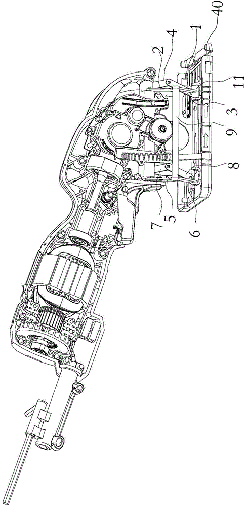
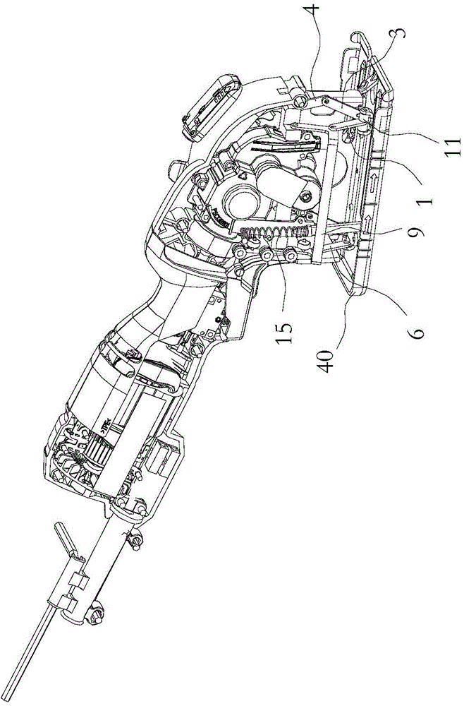
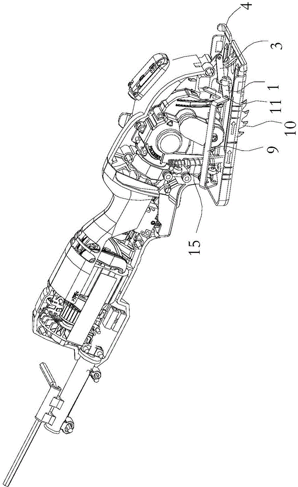
[0037] Such as Figure 1-2 As shown, a cutting control device for an electric circular saw in this embodiment is fixed on the base plate 40 of the electric circular saw and includes a saw blade support assembly connected to the base plate 40 and the saw blade assembly.

[0038] The saw blade support assembly controls the movement trajectory of the saw blade assembly relative to the bottom plate 40 to be vertical through the connecting rod and the hinge mechanism 11 connecting the connecting rod.

[0039] In one embodiment, the cutting control device for the electric circular saw further includes an elastic component for supporting the saw blade component and the bottom plate 40 .

[0040] Such...


PUM


Abstract

The invention discloses an electric circular saw cutting control device. The electric circular saw cutting control device is fixed to a bottom plate of an electric circular saw and comprises a saw blade supporting assembly which is connected with the bottom plate and a saw blade assembly. The saw blade supporting assembly controls the moving track of the saw blade assembly relative to the bottom plate to be perpendicular through a connecting rod and a hinge mechanism connected with the connecting rod. The saw blade supporting assembly comprises a first end supporting assembly and a second end supporting assembly, wherein the first end supporting assembly is used for supporting the front end of the saw blade assembly so that the moving track of the front end of the saw blade assembly relative to the bottom plate can be perpendicular, and the second end supporting assembly is used for supporting the rear end of the saw blade assembly so that the moving track of the rear end of the saw blade assembly relative to the bottom plate can be perpendicular. A saw blade moves perpendicularly relative to the bottom plate during cutting of the electric circular saw, the situation that the moving track of a saw blade in the prior art is an arc is changed, and therefore cutting can be more accurate and precise, the visibility effect is improved through the simple connecting rod design, and the cutting process is convenient to control.

Description

technical field [0001] The invention relates to the field of electric tools, in particular to a cutting control device for an electric circular saw. Background technique [0002] The electric circular saw is a tool that uses a single-phase series-excited motor as the power to drive the circular saw blade through the transmission mechanism for sawing operations. It has the characteristics of safety, reliability, reasonable structure, and high work efficiency. Suitable for sawing wood, fibreboard, plastic and flexible cables and similar materials. [0003] Generally, the slide rail part of the electric circular saw realizes the downward cutting action of the saw blade through the movement of the bearing in the arc groove. During the cutting process of the saw blade, the trajectory is arc, and the vertical linear motion cannot be realized; the visibility is poor. Difference. In the occasions that require high cutting precision, it is a huge test for the experience of the oper...

Claims


Application Information

Patent Timeline
IPC IPC(8): B25F5/00B23D45/16B27B9/00B26B25/00
Inventor 吉绍山陈国军张家良
Owner POSITEC POWER TOOLS (SUZHOU) CO LTD
Why Eureka
Eureka Blog
Learn More