Plastic hose automatic cutting device

A technology of automatic cutting device and plastic hose, which is applied in metal processing and other directions, can solve the problems of time-consuming and labor-consuming, low processing efficiency, and poor accuracy of manual tool setting, so as to improve the fixing effect, improve work efficiency and save costs. Effect

Active Publication Date: 2017-12-19
SHANGHAI JIAO TONG UNIV
View PDF7 Cites 0 Cited by
  • Summary
  • Abstract
  • Description
  • Claims
  • Application Information

AI Technical Summary

Problems solved by technology

The above-mentioned process is mostly manually operated, which is time-consuming and labor-intensive, and has the following disadvantages: 1. Manually locking and releasing the three-jaw clamping workpiece, the placement position changes greatly, and the processing error is large; 2. Manual tool setting has poor accuracy and poor repeatability; 3. When cutting both ends of the hose, it needs to be placed and placed repeatedly. Fixing again will easily cause uneven edges, resulting in increased processing errors and low overall processing efficiency.
However, the clamping structure in this technology is not suitable for clamping plastic hoses, and cannot be used for cutting plastic hoses

Method used


Image

  • Plastic hose automatic cutting device
  • Plastic hose automatic cutting device
  • Plastic hose automatic cutting device

Examples


Embodiment 1

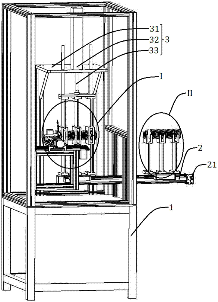
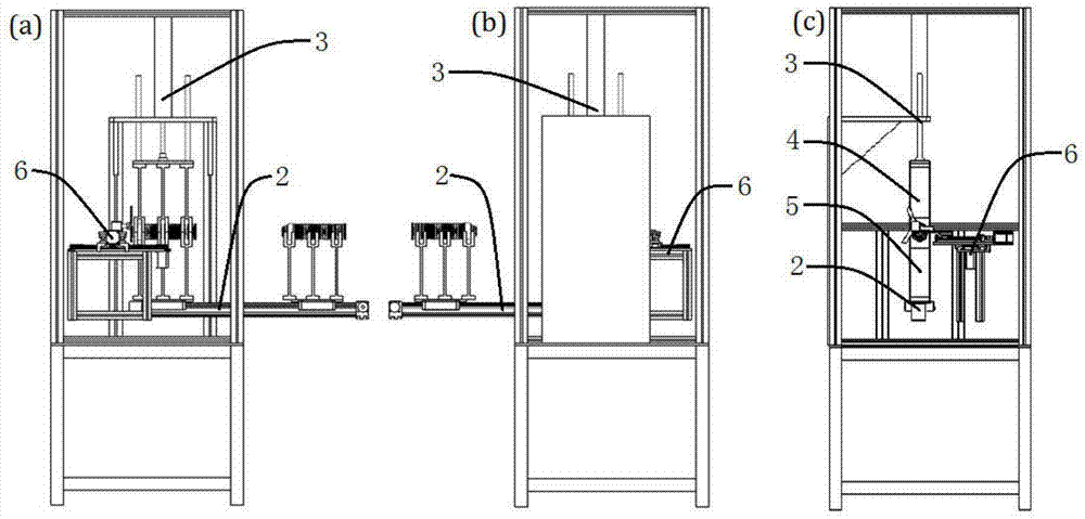
[0025] Such as figure 1 with figure 2 As shown, this embodiment includes: a frame 1, a rack material guide rail 2, an electric push rod 3, an upper fixing mechanism 4, a lower fixing mechanism 5 and a cutting mechanism 6, wherein: the rack material guide rail 2 and the cutting mechanism 6 are relatively arranged and fixed On the frame 1, the electric push rod 3 is slidingly connected with the frame 1, the bottom of the upper fixing mechanism 4 is fixedly connected with the electric push rod 3, and the bottom of the lower fixing mechanism 5 is fixedly connected with the frame guide rail 2;

[0026] The upper fixing mechanism 4 and the lower fixing mechanism 5 are of symmetrical structure, and the two pieces cooperate with each other and are fixed by clamping molds.

[0027] The racking material guide rail 2 is provided with a guide rail motor 21, and the guide rail motor 21 drives the racking material guide rail 2 to rotate and convert it into a horizontal linear reciprocatin...

Embodiment 2

[0035] Such as Image 6 As shown, according to the different cutting objects, the structure of the upper fixing mechanism 4 and the lower fixing mechanism 5 can be changed accordingly; when the cutting object is a smooth plastic hose, in order to fix it, the upper fixing mechanism 4 and the lower fixing mechanism Mechanism 5 is designed as an integral structure, and the internal size is determined according to the cutting object; the internal shape of upper fixing mechanism 4 and lower fixing mechanism 5 can also be an infinitely enlarged trapezoidal cylinder, so as to realize the cutting of irregular soft bodies.

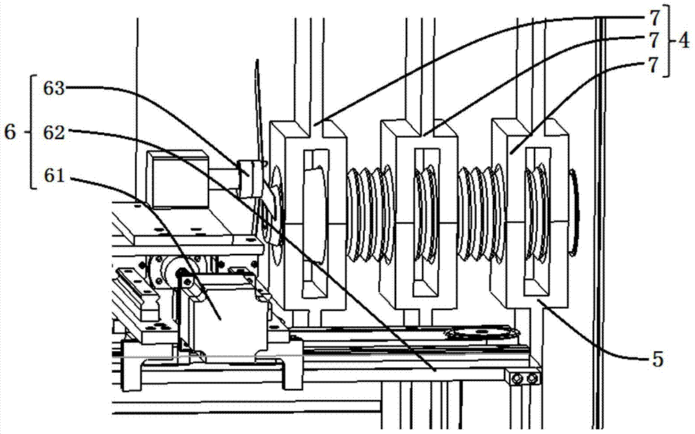
[0036] Such as Figure 7 with Figure 8 As shown, the upper fixing mechanism 4 and the lower fixing mechanism 5 are all integrally formed, including: support plates 81 on both sides and several support clamping plates 82 connecting the support plates 81 on both sides; the support plates 81 are provided with The draw-in slot 83 that the frame guide rail 2 and the ...


PUM


Abstract

The invention belongs to the technical field of plastic pipe machining and discloses an automatic cutting device for plastic hoses. Through the automatic cutting device, the cutting lengths can be set. The automatic cutting device comprises a rack, a material supporting guide rail, an electric push rod, an upper fixing mechanism, a lower fixing mechanism and a cutting mechanism. The material supporting guide rail and the cutting mechanism are oppositely arranged and fixed to the rack. The electric push rod and the rack are connected in a sliding mode. The bottom of the upper fixing mechanism is fixedly connected with the electric push rod. The bottom of the lower fixing mechanism is fixedly connected with the material supporting guide rail. The upper fixing mechanism and the lower fixing mechanism are of a symmetrical structure, fixed in a die-combining mode, and provided with mutually matched limiting grooves correspondingly. According to the automatic cutting device for the plastic hoses, overall fixation of the plastic hoses with different shapes and lengths can be achieved, meanwhile, according to the set cutting lengths, redundant materials at the two ends of the plastic hoses are cut fast, and the cutting precision and cutting efficiency are high.

Description

technical field [0001] The invention relates to a technology in the field of plastic pipe processing, in particular to an automatic cutting device for plastic hoses that can set the cutting length. Background technique [0002] In the current plastic hose processing, it is necessary to separate the mold in the injection molding machine, then take out the product, measure the size according to the required length and mark the line, and finally fix it on the three claws of the small lathe, rotate the machine tool spindle, and manually feed the tool and other processes to cut off the excess length or corners of the formed plastic hose. The above-mentioned process is mostly manually operated, which is time-consuming and labor-intensive, and has the following disadvantages: 1. Manually locking and releasing the three-jaw clamping workpiece, the placement position changes greatly, and the processing error is large; 2. Manual tool setting has poor accuracy and poor repeatability; ...

Claims


Application Information

Patent Timeline
Patent Type & Authority Patents(China)
IPC IPC(8): B26D1/12B26D5/08B26D7/02B26D7/06
CPCB26D1/12B26D5/086B26D7/02B26D7/0608
Inventor 陈自强陆崇清庞超飞郑昌文葛云龙
Owner SHANGHAI JIAO TONG UNIV
Why Eureka
Try Eureka