Hub driving assembly

A wheel drive and assembly technology, applied in the direction of the wheel hub, motion deposition, power device, etc., can solve problems such as interference and space occupation, and achieve the effect of layout optimization

Inactive Publication Date: 2016-06-22
SCHAEFFLER TECH AG & CO KG
View PDF5 Cites 1 Cited by
  • Summary
  • Abstract
  • Description
  • Claims
  • Application Information

AI Technical Summary

Problems solved by technology

[0005] In the design and assembly of the vehicle, the design and layout of the hub drive and the brake are very complicated and strict. However, in the prior art, the brake is set up separately from the hub drive, which takes up too much space and causes the entire system to move outwards from the wheel. extension, which can easily cause interference with the vehicle suspension system

Method used


Image

  • Hub driving assembly
  • Hub driving assembly
  • Hub driving assembly

Examples


Embodiment Construction

[0028] In order to make the above objects, features and advantages of the present invention more comprehensible, specific embodiments of the present invention will be described in detail below in conjunction with the accompanying drawings.

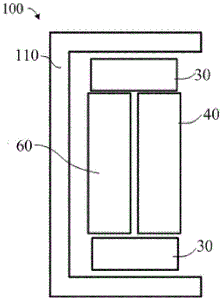
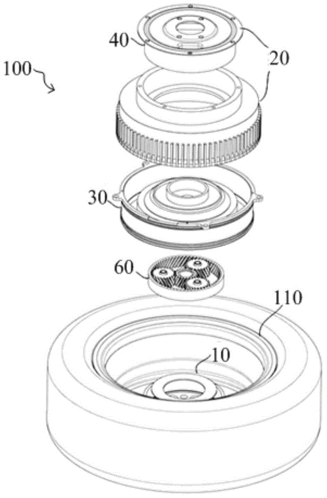
[0029] refer to Figure 2-4 , the wheel hub drive assembly 100 of the present embodiment comprises: a wheel hub 110; a wheel hub bearing 10, located in the wheel hub and arranged on the central axis, wherein the bearing inner ring 11 of the wheel hub bearing 10 is a rotating ring and connected to the wheel hub 110, and the bearing The outer ring 12 is a non-rotating ring; the housing 20 is located between the hub bearing 10 and the hub 110, and forms a housing space around the hub bearing 10, the housing space includes a first storage room, a second storage room and a third storage room The housing 20 axially includes: a first housing 201, a second housing 202, a third housing 203 located between the first housing 201 and the second housin...


PUM


Abstract

A hub driving assembly includes a hub, a hub bearing positioned in the hub and arranged on a central axis of the hub, a housing positioned between the hub bearing and the hub and forming a housing space around the hub bearing; the housing space includes a first accommodation chamber and a second accommodation chamber; the housing, in the axial direction, at least includes two parts, and an outermost part in the axial direction of the housing serves as a side wall of the second accommodation chamber; drivers are positioned in the first accommodation chamber, output ends of the drivers extend out of the first accommodation chamber and then are connected to the hub; a brake is positioned in the second accommodation chamber and is arranged in the outermost part in the axial direction of the housing, and an output end of the brake is connected to the hub; support pieces are positioned in the second accommodation chamber, and the support pieces support the hub bearing and housing parts near the outermost part in the axial direction of the housing in the radial direction. According to the scheme, the brake is integrated into the hub drivers, and then layout of the hub drivers and the brake is optimized in a limited housing space; and the support pieces can support the housing parts near the outermost part in the axial direction of the housing, and then prevent the housing parts from inclining and falling apart.

Description

technical field [0001] The invention relates to the technical field of automobiles, in particular to a wheel hub drive assembly. Background technique [0002] In-wheel motor technology, also known as in-wheel motor technology, is characterized by the integration of power, transmission and braking devices into the wheel hub, thus greatly simplifying the mechanical parts of electric vehicles. [0003] Wherein the power device adopts the hub drive, and the motor is directly installed in the hub of the wheel. When the wheels are driven, the wheel hub drive outputs drive torque to the wheels; when the wheels are braked, it is realized by a brake installed outside the wheel hub drive. [0004] In the prior art, there is a hub drive with a wheel-side reducer, which includes a motor and a reducer connected to the motor. Such as figure 1 As shown, the wheel hub drive includes: a motor 1 located in the hub (not marked in the figure) and a reducer 2 located at the output end of the ...

Claims


Application Information

Patent Timeline
IPC IPC(8): B60B27/00B60K7/00
Inventor 高志川黄超蔡向阳惠艳翠
Owner SCHAEFFLER TECH AG & CO KG
Why Eureka
Try Eureka