Vehicle-mounted automatic charging mechanical arm and electric vehicle carried with same

A technology for automatic charging and electric vehicles, applied in the direction of electric vehicles, electric vehicle charging technology, charging stations, etc., can solve the problems of failure to fully realize the intelligent charging of electric vehicles, low flexibility and practicability of charging devices, and insufficient space utilization Sufficient and other issues to achieve the effect of avoiding safety hazards and wrong operations, light weight, and ensuring charging needs

Inactive Publication Date: 2016-06-22
SHANGHAI INT AUTOMOBILE CITY GRP CO LTD +1
View PDF7 Cites 20 Cited by
  • Summary
  • Abstract
  • Description
  • Claims
  • Application Information

AI Technical Summary

Problems solved by technology

[0004] Chinese Patent Publication No. CN104795868A discloses an automatic charging system for electric vehicles. The charging plug of the electric vehicle is inserted into or pulled out of the charging socket through an independent mobile charging plug automatic plugging device, which solves the problem of manually plugging and unplugging the charging plug for electric charging. There are potential safety hazards in the car charging operation. The above-mentioned automatic charging device installed on the parking space must solve the problems of waterproofing and anti-theft, and it is not easy to maintain.
There are documents disclosing automatic charging devices for electric vehicles, but they are all designed in combination with existing charging piles. Not high, failed to fully realize the intelligence of electric vehicle charging

Method used


Image

  • Vehicle-mounted automatic charging mechanical arm and electric vehicle carried with same
  • Vehicle-mounted automatic charging mechanical arm and electric vehicle carried with same
  • Vehicle-mounted automatic charging mechanical arm and electric vehicle carried with same

Examples


Embodiment Construction

[0042] The following will clearly and completely describe the technical solutions in the embodiments of the present invention with reference to the drawings in the embodiments of the present invention. Obviously, the described embodiments are part of the embodiments of the present invention, not all of them. Based on the embodiments of the present invention, all other embodiments obtained by persons of ordinary skill in the art without making creative efforts shall fall within the protection scope of the present invention.

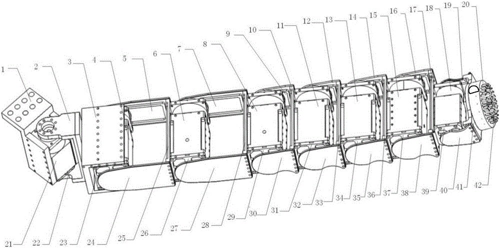
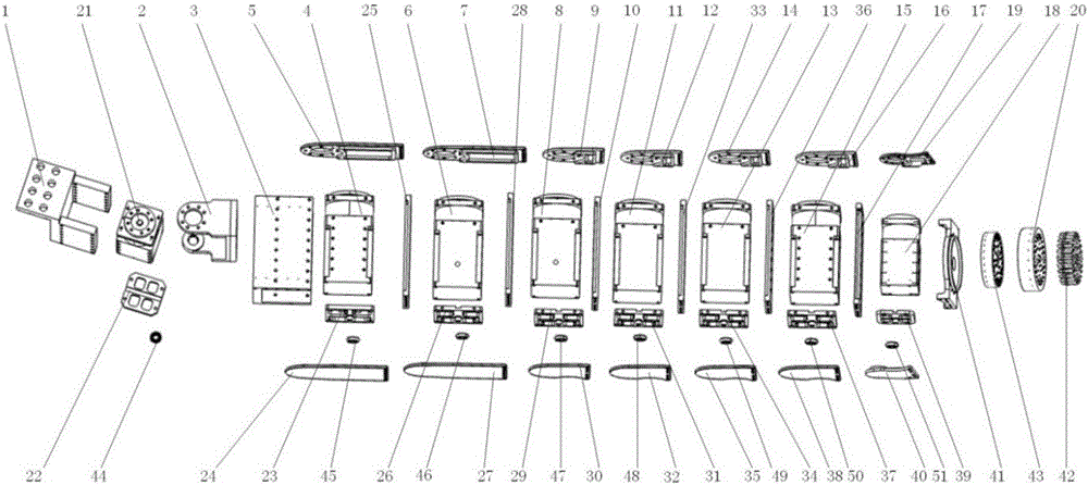
[0043] Such as figure 1 and 2 As shown, a vehicle-mounted automatic charging manipulator is mainly composed of a manipulator body, a driving device (industrial grade digital steering gear) and a control part. The mechanical arm is made of aluminum alloy material.

[0044] The composition of the mechanical arm:

[0045] The main body of the robotic arm is composed of the swing arm fixing plate 1, the first joint, seven parallel joints, the end plug and t...


PUM


Abstract

The invention relates to a vehicle-mounted automatic charging mechanical arm and an electric vehicle carried with the mechanical arm. The mechanical arm is arranged at the bottom of the electric vehicle, and automatic charging of the electric vehicle is achieved by plugging the mechanical arm into a socket automatically. The mechanical arm comprises a swing arm fixing plate, a first joint, a parallel joint unit, a plug and a camera, wherein one end of the swing arm fixing plate is fixed to the bottom of the electric vehicle; one end of the first joint is connected with the other end of the swing arm fixing plate; one end of the parallel joint unit is connected with the other end of the first joint; the parallel joint unit is parallel to a chassis of the vehicle when the electric vehicle is not charged, and is moved downwards when the electric vehicle needs to be charged; the plug is mounted at the tail end of the parallel joint unit; and the camera is mounted on one side face of the plug. Compared with the prior art, automatic charging is realized, a charging device is small in size, and using is convenient. The vehicle-mounted automatic charging mechanical arm fills up the blank in China and is of great significance on promoting the technological development of electric vehicles.

Description

technical field [0001] The invention relates to the technical field of automatic charging of electric vehicles, in particular to a vehicle-mounted automatic charging mechanical arm and an electric vehicle carrying the mechanical arm. Background technique [0002] With the gradual promotion and use of electric vehicles, the safety and convenience of electric vehicle charging has become an issue that must be paid attention to during the promotion of electric vehicles, especially for leased or other dedicated electric vehicles. Users need to do it by themselves after parking. On the one hand, there are potential safety hazards in manual operation. On the other hand, many users have not yet developed the habit of charging at will or do not know how to plug in and out the charging plug. Moreover, the existing charging facilities are too large, lack unified management, and rely on manual operation. [0003] Therefore, for electric vehicles, it is an important issue to ensure that...

Claims


Application Information

Patent Timeline
IPC IPC(8): B60L11/18
CPCB60L53/00B60L53/14B60L53/35Y02T10/70Y02T10/7072Y02T90/12Y02T90/14
Inventor 曹光宇施莹金勇喻杰韦东波狄士春
Owner SHANGHAI INT AUTOMOBILE CITY GRP CO LTD
Why Eureka
Try Eureka