Film pasting method, film pasting device and display screen

A technology of a film sticking device and a display screen, which is applied in packaging and other directions, can solve the problems of limited alignment accuracy, difficulty in ensuring the alignment of the optical film 12, and affecting the aesthetics of the screen 11, etc.

Active Publication Date: 2016-06-22
TRULY OPTO ELECTRONICS
View PDF4 Cites 1 Cited by
  • Summary
  • Abstract
  • Description
  • Claims
  • Application Information

AI Technical Summary

Problems solved by technology

However, no matter which of the above-mentioned film pasting methods is adopted, the size of the optical film pasted on the surface of the screen needs to be smaller than the size of the screen, such as figure 1 As shown, this is due to the limited alignment accuracy when manually or mechanically attaching the film; if the size of the optical film 12 attached to the surface of the screen 11 is consistent with the screen 11, it is difficult to apply the film automatically or manually by manipulator. Ensure that the optical film 12 is perfectly aligned with the screen 11
The problem that the size of the optical film 12 attached to the surface of the screen 11 is smaller than the size of the screen 11 is: after the optical film 12 is attached to the surface of the screen 11, there is a gap between the optical film 12 and the screen 11. Steps 13 will be formed, which will affect the aesthetics of the screen 11; and once the part of the screen 11 not bonded by the optical film 12 is broken, it may cause harm to the user

Method used


Image

  • Film pasting method, film pasting device and display screen
  • Film pasting method, film pasting device and display screen
  • Film pasting method, film pasting device and display screen

Examples


Embodiment Construction

[0058] As mentioned in the background, the film sticking method in the prior art cannot realize that the optical film completely covers the surface of the screen and is fully bonded to the screen.

[0059]In view of this, an embodiment of the present invention provides a method for pasting a film, which is applied to a screen surface film, including:

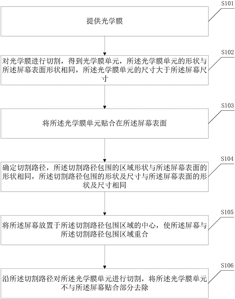
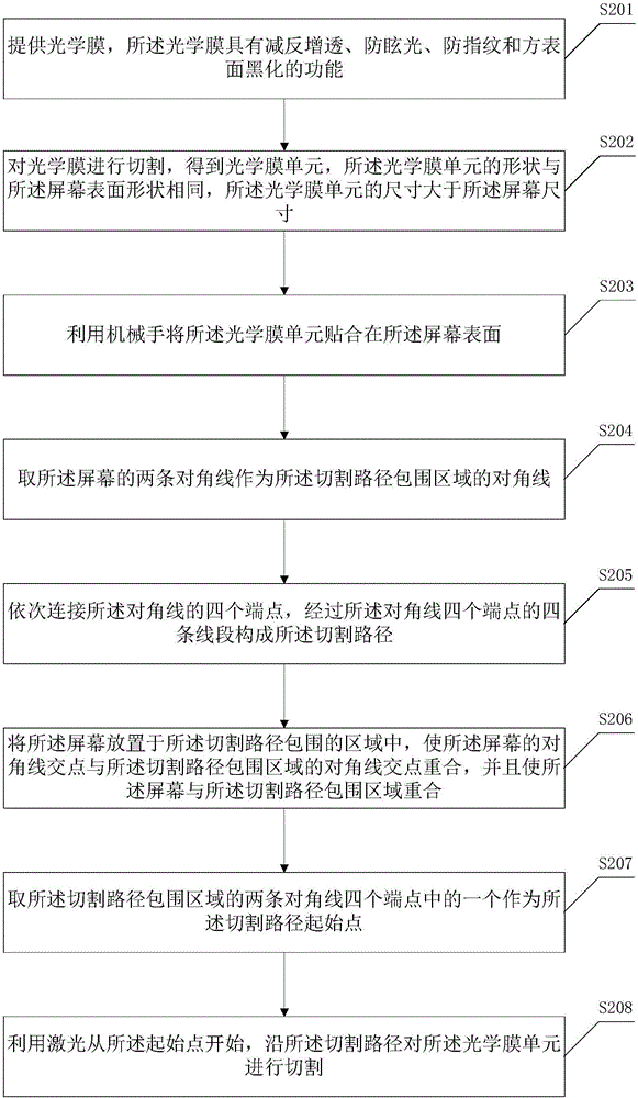
[0060] Provide optical film;

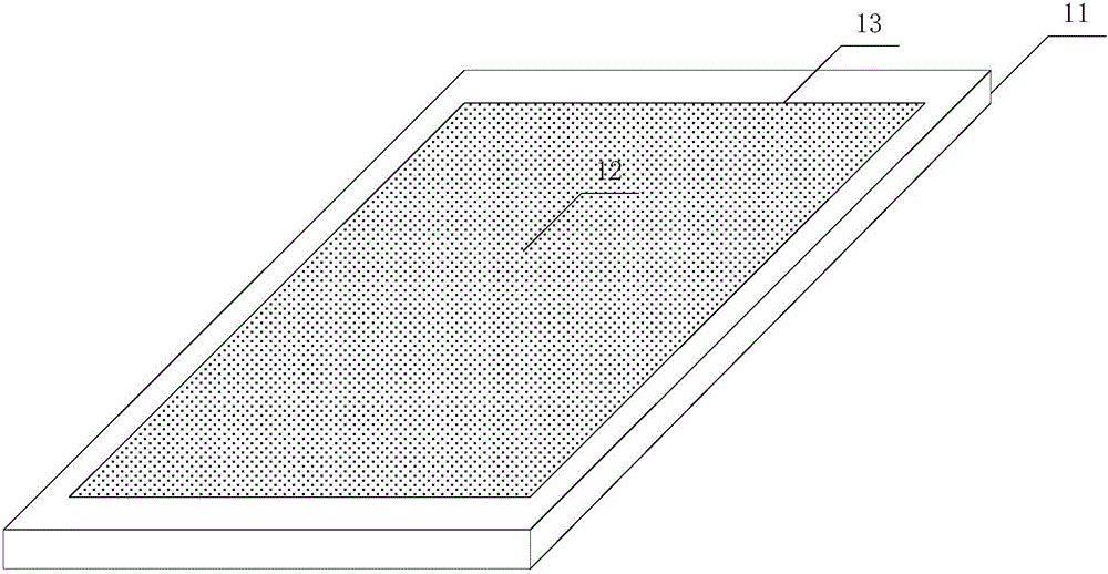
[0061] cutting the optical film to obtain an optical film unit, the shape of the optical film unit is the same as the surface shape of the screen, and the size of the optical film unit is larger than the screen size;

[0062] attaching the optical film unit to the screen surface;

[0063] Determine a cutting path, the shape of the area surrounded by the cutting path is the same as the shape of the screen surface, and the shape and size surrounded by the cutting path are the same as the shape and size of the screen surface;

[0064] placing the screen at the center of the cutting path enclosing ar...


PUM


Abstract

The invention discloses a film pasting method, a film pasting device and a display screen. According to the film pasting method, firstly, an optical film is cut to an optical film unit, the shape of the optical film unit is the same with that of the screen surface, the size of the optical film unit is larger than the size of the screen, and the optical film unit is glued to the screen surface; the cutting path is determined, the screen is placed on the center of the surrounding area of the cutting path, the shape of the surrounding area of the cutting path is the same with that of the screen surface, and the shape size of the surrounding area of the cutting path is the same with that of the screen surface; and finally, the optical film unit is cut along the cutting path, and the part, not glued to the screen, of the optical film unit is removed. Through the flow, it is found that the film pasting method ensures that the optical film unit completely covers the screen surface, and is completely glued to the screen, and the attractiveness degree and safety of the screen are improved.

Description

technical field [0001] The invention relates to the technical field of automatic control, and more specifically, relates to a film sticking method, a film sticking device and a display screen. Background technique [0002] With the continuous progress of society, electronic equipment has penetrated into every aspect of people's life, and the screen of the electronic equipment is one of the main devices for the electronic equipment to interact with user information. Before the screen leaves the factory and is used, it is necessary to carry out lamination operations of different types of optical films on its surface or to carry out surface treatment on the screen, so that the surface of the screen has one or more of the functions of anti-glare, anti-reflection, and anti-fouling. However, the method of attaching an optical film on its surface has become the mainstream screen processing method due to its convenience and quickness. [0003] In the prior art, methods for sticking...

Claims


Application Information

Patent Timeline
Patent Type & Authority Applications(China)
IPC IPC(8): B65B33/02
CPCB65B33/02
Inventor 张文庆刘源张涛涛李锋林树茂李志成李建华
Owner TRULY OPTO ELECTRONICS
Why Eureka
Try Eureka