Multifunctional power field transmitting facility

A transmission facility and multi-functional technology, applied in the field of power facility planning, can solve problems such as unsatisfactory safety guarantee of sealing structure or unsatisfactory operation convenience, resource occupation, high staffing and construction costs, and inability to clamp well, etc., to achieve Good fixing effect, improving construction quality and efficiency, convenient and fast fixing effect

Inactive Publication Date: 2016-06-22
STATE GRID CORP OF CHINA +1
View PDF7 Cites 9 Cited by
  • Summary
  • Abstract
  • Description
  • Claims
  • Application Information

AI Technical Summary

Problems solved by technology

[0005] 3) The existing various high-altitude cable fixing mechanisms, such as the ladder head and other structures, generally adopt the method of hanging by using their own weight. The sealing structure at the hook mouth is not ideal in terms of safety guarantee or convenient operation. Due to natural factors such as strong winds, or the vibration of the cable, it shakes, the stability is poor, and it cannot be clamped well.
[0006] 4) The existing power facilities need to be transferred by means of transportation and vehicles, which makes the resource occupation, staffing and construction costs higher, and brings inconvenience to the work

Method used


Image

  • Multifunctional power field transmitting facility
  • Multifunctional power field transmitting facility
  • Multifunctional power field transmitting facility

Examples


Embodiment 1

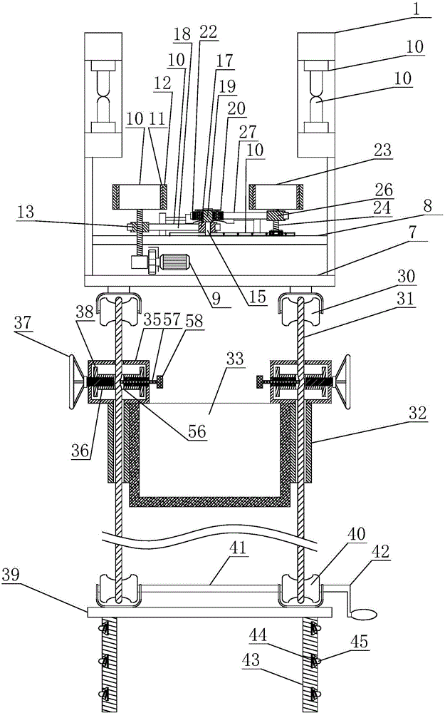
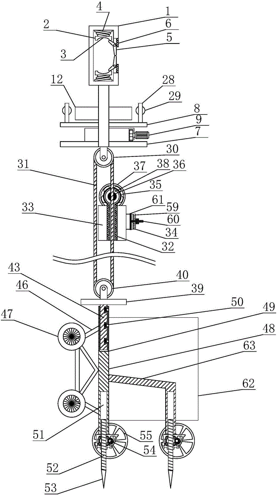
[0039] Embodiment 1: The present invention is a multifunctional electric power on-site transmission facility, the main structure includes a high-altitude mechanism and a ground mechanism:

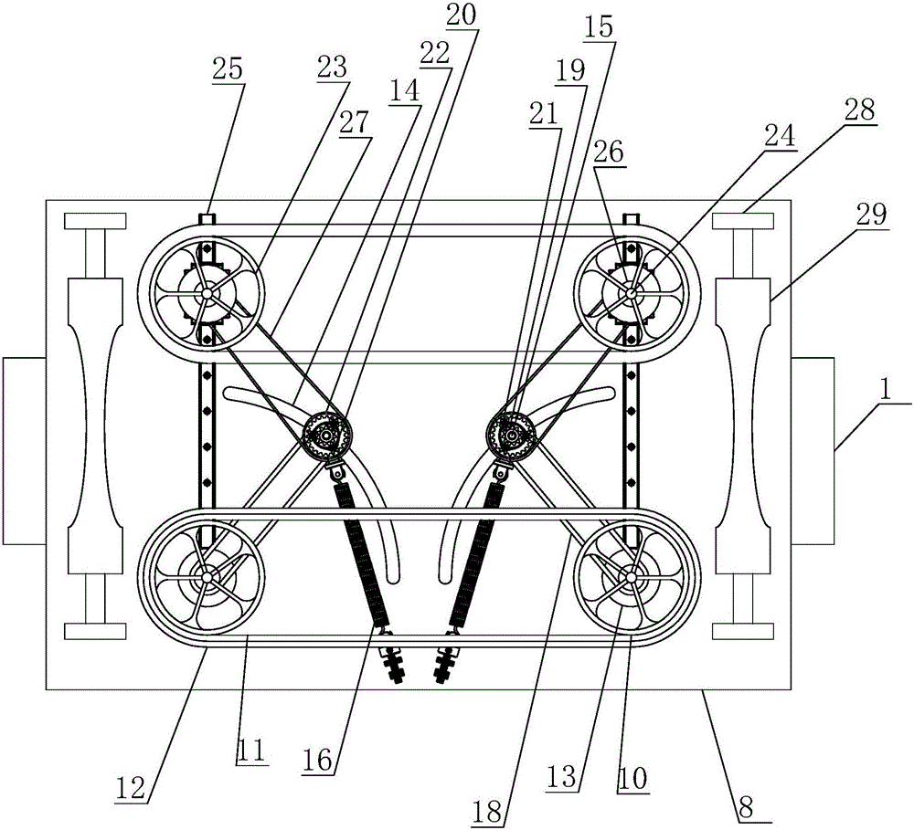
[0040] The high-altitude mechanism includes a rectangular frame body 1 arranged at the top. The rectangular frame body 1 is two and horizontally symmetrically arranged. The middle part of one side of the rectangular frame body 1 is provided with an opening. The top of the rectangular frame body 1 And the bottom is provided with a rubber clip 2, the inner side of the rubber clip 2 is provided with an arc-shaped clip groove 3, and the outer side of the rubber clip 2 is provided with a compression spring 4, and the compression spring 4 is far away from the rubber clip 2. One end is connected with the rectangular frame body 1, and the opening of the rectangular frame body 1 is provided with a trigger baffle 5 symmetrically up and down, and the trigger baffle 5 is a V-shaped plate with an obtuse ...

Embodiment 2

[0044] Embodiment 2 The present invention is a multi-functional power on-site transmission facility, the main structure includes a high-altitude mechanism and a ground mechanism:

[0045] The high-altitude mechanism includes a rectangular frame body 1 arranged at the top. The rectangular frame body 1 is two and horizontally symmetrically arranged. The middle part of one side of the rectangular frame body 1 is provided with an opening. The top of the rectangular frame body 1 And the bottom is provided with a rubber clip 2, the inner side of the rubber clip 2 is provided with an arc-shaped clip groove 3, and the outer side of the rubber clip 2 is provided with a compression spring 4, and the compression spring 4 is far away from the rubber clip 2. One end is connected with the rectangular frame body 1, and the opening of the rectangular frame body 1 is provided with a trigger baffle 5 symmetrically up and down, and the trigger baffle 5 is a V-shaped plate with an obtuse angle, an...


PUM


Abstract

The invention discloses a multifunctional power field transmitting facility, and mainly relates to the field of power facility planning. The multifunctional power field transmitting facility comprises rectangular frames hooked and hung on cables. Triggering baffles are hinged to the positions of openings of the rectangular frames. The inner ends of the triggering baffles press rubber clamping blocks with compression springs. A connecting plate is arranged below the rectangular frames and provided with a feeding platform. The feeding platform is provided with rubber belt tracks used for clamping and pushing the cables. Bearing pulleys are arranged below the connecting plate, the cables are wound around the bearing pulleys, the lower ends of the cables are wound around fixed pulleys, and the cables are provided with a lifting hopper. The fixed pulleys are installed on a fixing plate, and inserting columns are arranged on the bottom face of the fixing plate. The multifunctional power field transmitting facility further comprises fixing columns matched with the inserting columns. Spearheads capable of ascending and descending are arranged at the bottom ends of the fixing columns, and trundles are arranged on one sides of the fixing columns. The multifunctional power field transmitting facility has the beneficial effects that the cables can be stably pushed from the high position, conveying of objects and the cables between the high position and the ground can be finished, and the self-conveying function is achieved as well.

Description

technical field [0001] The invention relates to the field of power facility planning, in particular to a multifunctional power on-site transmission facility. Background technique [0002] At present, with the increasingly accelerated urban infrastructure construction across the country, the power distribution facilities between cities and towns have been repeatedly expanded. During the construction of power facility planning sites, construction personnel are often required to carry out surveys, maintenance, and operations on high-altitude cables. The following situations are often encountered : [0003] 1) In electric power construction, the commonly used construction configuration is generally to use tractors, traction swivels, pulley blocks, cable conveyors, pay-off brackets and other facilities for cable traction. However, these facilities are basically erected on the bottom surface. When sending and erecting wires at high places, it can only be used with pulley blocks a...

Claims


Application Information

Patent Timeline
Patent Type & Authority Applications(China)
IPC IPC(8): B65H75/38B65H75/44
CPCB65H75/38B65H75/44
Inventor 刘伟周彬崔雅平吕永喜王春丽刘永涛
Owner STATE GRID CORP OF CHINA
Why Eureka
Try Eureka