
A slotting equipment for thermal insulation and decorative composite board

A slotting equipment and composite board technology, which is applied in the direction of construction and building construction, can solve problems such as difficult control accuracy, slot burst, depth and width accuracy, etc., to reduce labor intensity of workers, slotting position, etc. Accurate and reduce the effect of defective product rate

Active Publication Date: 2018-08-31
ASIA CUANON TECH SHANGHAI
View PDF6 Cites 0 Cited by
  • Summary
  • Abstract
  • Description
  • Claims
  • Application Information

AI Technical Summary

Problems solved by technology

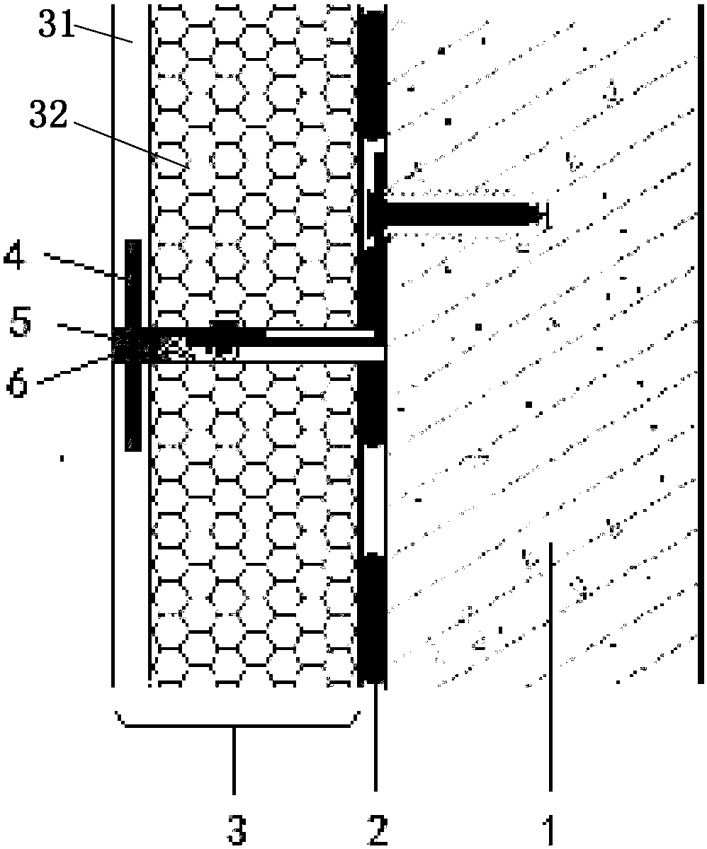
[0005] Although this surface anchoring installation method is safer, the anchor installation grooves used for anchoring are all manually slotted on site. The general practice is that construction workers on the construction site use ordinary portable cutting machines, or use ordinary cutting machines vertically. It is directly fixed on a table or shelf and converted into a simple device to perform slotting operations directly. This simple slotting operation brings many safety hazards and many problems to this surface anchoring installation method:
[0006] 1. Due to the thinness of the decorative panel, in order to achieve the required anchoring effect, there are high requirements for the accuracy of the slotting position, slotting depth and slotting width. However, due to the manual slotting on the construction site, it is manually controlled by workers , so that the accuracy of the slotting position, depth and width has been greatly affected, and the slot body often bursts, the slot body is not parallel to the plate surface, and the anchor cannot be installed, the slot body is too small or too large, and the slot body is too large. Close to the panel, the finish is damaged, the tank is too close to the insulation layer, resulting in low anchoring force, or the anchoring effect cannot be achieved directly on the insulation layer, which affects the bearing capacity of the anchor.
Considering the self-weight of the thermal insulation and decorative composite panels and the requirements for flatness, it is easy to cause safety hazards and aesthetic problems of the thermal insulation and decorative composite panels;
[0007] 2. Due to the requirement of the number of anchors, two or more grooves are generally required to be opened on the same side of the thermal insulation and decorative composite board. The above-mentioned groove method only has one blade, and only one groove can be opened at a time. The work efficiency is low, which affects the construction progress and increases the labor cost and labor intensity of the workers
[0008] 3. When an anchor can fix two adjacent thermal insulation and decorative composite panels up and down or left and right at the same time, it is required that the grooves on the corresponding sides of the adjacent two thermal insulation and decorative composite panels should be at the same position or the staggered distance should be within the error range , but it is difficult to control its accuracy by hand, which leads to the situation that workers cannot align when installing anchors
[0009] 4. The motor and cutting tool are exposed without any protective measures, and a large amount of dust is easily generated during cutting, which poses a serious threat to the personal safety and health of workers

Method used


Image

  • A slotting equipment for thermal insulation and decorative composite board
  • A slotting equipment for thermal insulation and decorative composite board
  • A slotting equipment for thermal insulation and decorative composite board

Examples


Embodiment Construction

[0032]In order to understand the above-mentioned purpose, features and advantages of the present invention more clearly, specific implementations according to the present invention will be described below with reference to the accompanying drawings. It should be noted that, in the case of no conflict, the embodiments of the present application and the features in the embodiments can be combined with each other.

[0033] In the following description, many specific details are set forth in order to fully understand the present invention. However, the present invention can also be implemented in other ways different from those described here. Therefore, the protection scope of the present invention is not limited by the specific details disclosed below. EXAMPLE LIMITATIONS.

[0034] Such as Figure 4 As shown, a thermal insulation and decorative composite panel grooving equipment according to an embodiment of the present invention includes a frame 71, a drive system 72, a contro...


PUM


Abstract

The invention provides grooving equipment for thermal insulating decorative composite boards. The grooving equipment comprises a rack, a driving system, a control system, an operation platform, a grooving cutter and a fixing device, wherein the driving system and the control system are mounted in a cabinet body; the operation platform is mounted at the top end of the cabinet body and can move forwards and backwards; the grooving cutter is mounted on the cabinet body, can rotate and move in up-down and left-right directions and is higher than the platform surface of the operation platform; the fixing device is mounted on the operation platform and positioned above the operation platform; the driving system is used for driving the grooving cutter and the operation platform; the control system is used for controlling the driving system, the operation platform and the grooving cutter; and a thermal insulating decorative composite board is tightly pressed on the operation platform by the fixing device. According to the grooving equipment for the thermal insulating decorative composite boards, the grooving cutter can be adjusted in the up-down and left-right directions so as to meet the grooving requirements of boards at different thicknesses and in different positions; by adopting the movable operation platform, the labor intensity of workers is reduced, and safety and reliability are ensured; and by adopting the automatic control system, grooving precision is improved, and the rate of defective products is reduced.

Description

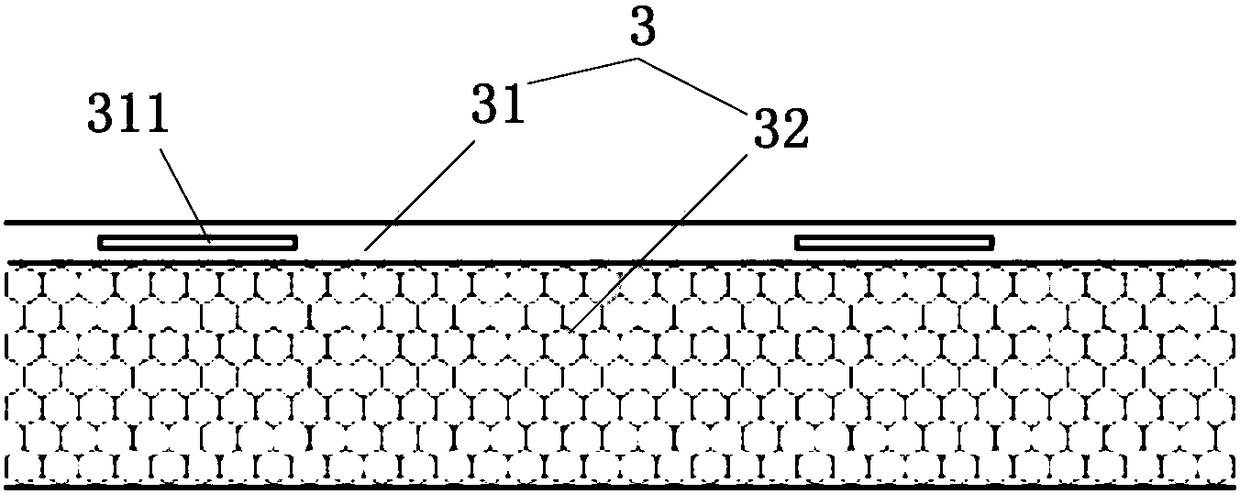
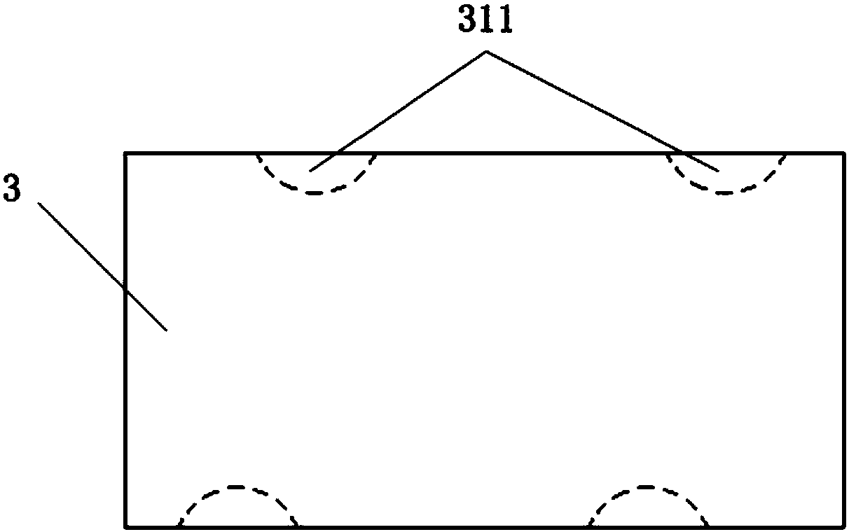
technical field [0001] The invention relates to a slotting mechanical device, in particular to slotting equipment for thermal insulation and decorative composite boards. Background technique [0002] Insulation and decoration composite board is a new type of exterior wall insulation and decoration material that has emerged in recent years. It has been gradually recognized and used by users due to its excellent thermal insulation effect and decorative effect. [0003] Such as figure 1 and figure 2 As shown, the thermal insulation and decorative composite board 3 is generally composed of a decorative panel 31 and an insulating layer 32, or is composed of a decorative panel 31, an insulating layer 32 and a bottom plate (not shown in the figure); wherein the decorative panel 31 is generally a belt Inorganic boards with paint finish, metal boards with paint finish, thin stone, ceramic boards, etc. Among these types of decorative panels, inorganic boards with paint finishes are...

Claims


Application Information

Patent Timeline
Patent Type & Authority Patents(China)
IPC IPC(8): E04F21/00
CPCE04F21/00E04F21/0046
Inventor 孙先海袁志良雷鹏徐志新李金钟
Owner ASIA CUANON TECH SHANGHAI
Learn More