
Supporting device

A technology of supporting devices and supporting rods, which is applied in the field preparation and construction of pillars and building components, which can solve the problems of high density of supporting parts, weak structural stability, poor structural stability, etc., and achieve high disassembly and assembly efficiency , the effect of enhanced bearing capacity and fewer supports

Inactive Publication Date: 2016-06-22
SNTO TECH GRP
View PDF5 Cites 8 Cited by
  • Summary
  • Abstract
  • Description
  • Claims
  • Application Information

AI Technical Summary

Problems solved by technology

However, the support system required for prefabricated concrete in the process of floor slab construction is relatively complicated.
For example, there are many supporting parts, including supporting rods, horizontal rods, inclined rods, etc., and the connecting parts used for connection also increase accordingly; at the same time, the arrangement density of supporting parts is high, resulting in reduced working space, which is not conducive to disassembly; In the support system, the wooden formwork used to carry the prefabricated parts of the floor is fixed to several support rods through the lap joint of the middle piece. Due to the influence of installation accuracy and bearing strength, the structural stability and strength of the entire support system are weak
Therefore, the support system of the related art has the disadvantages of many supports, high cost, low disassembly efficiency, poor structural stability and low strength

Method used


Image

  • Supporting device
  • Supporting device
  • Supporting device

Examples


Embodiment Construction

[0024] In order to facilitate the understanding of the present invention, the present invention will be described more fully below with reference to the associated drawings. Preferred embodiments of the invention are shown in the accompanying drawings. However, the present invention can be embodied in many different forms and is not limited to the embodiments described herein. On the contrary, these embodiments are provided to make the understanding of the disclosure of the present invention more thorough and comprehensive.

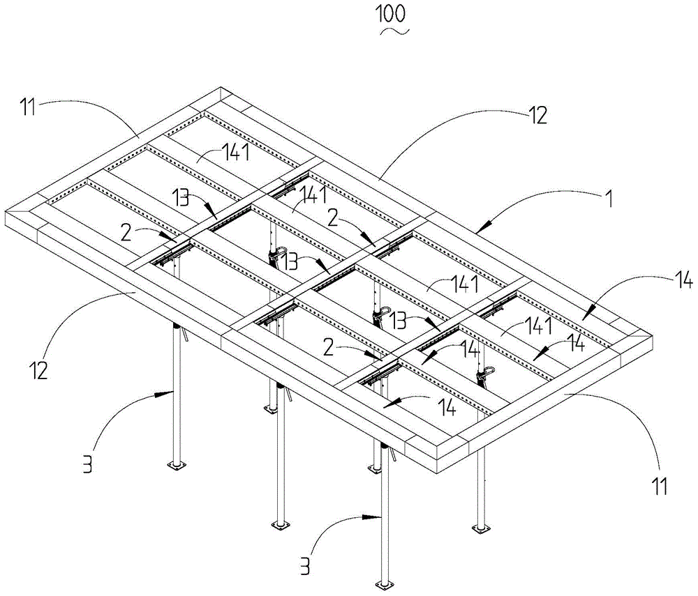
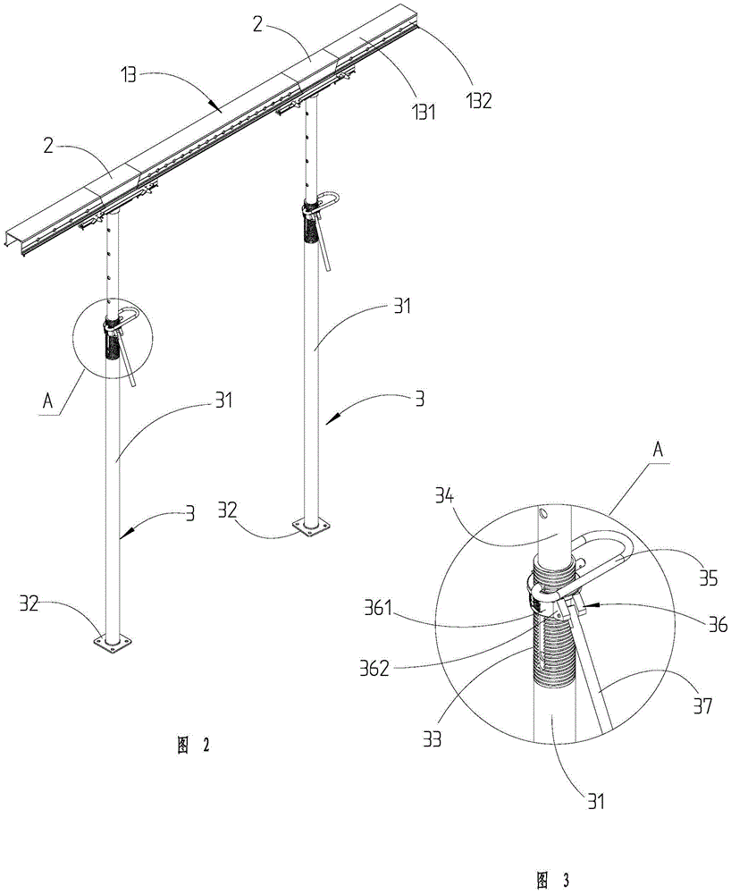
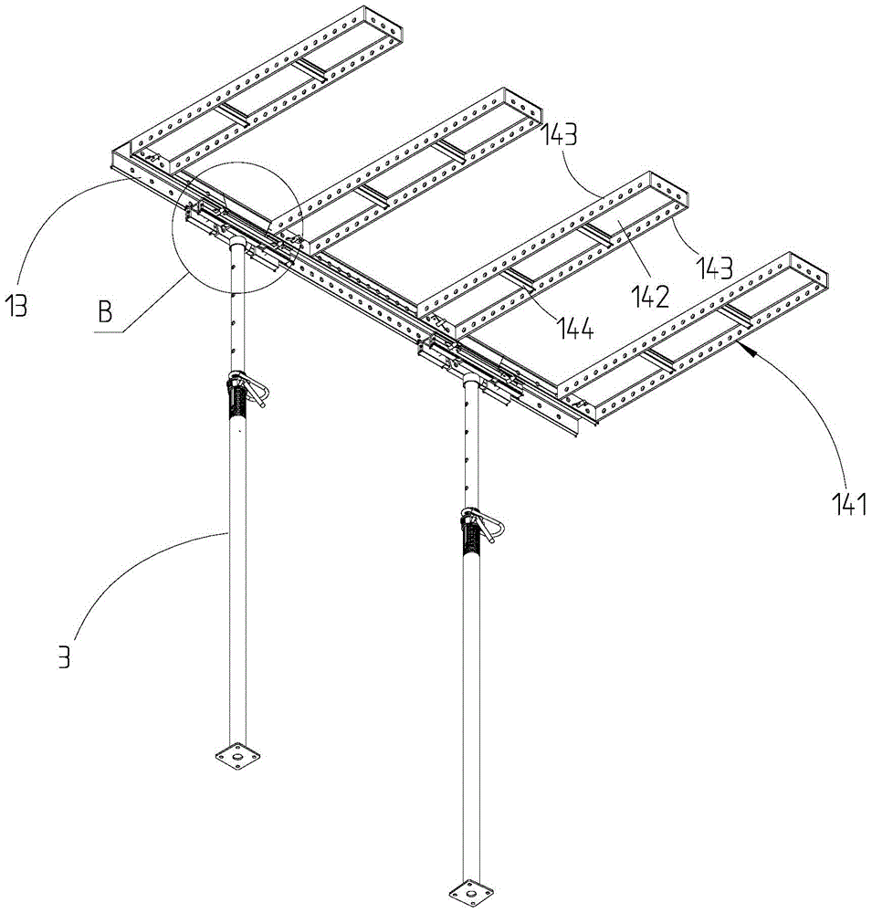
[0025] refer to Figure 1-Figure 8 As shown, in an embodiment of the present invention, a supporting device 100 includes a carrying unit 1 , a plurality of jacking units 2 and a plurality of telescopic support rods 3 . The bearing unit 1 includes a main frame, several first keels 13 and several second keels 14 . The main frame includes two parallel first frame bars 11 and two parallel second frame bars 12 . Both ends of the second frame bar 12 are ver...


PUM


Abstract

The invention provides a supporting device. The supporting device comprises a bearing unit, a plurality of jacking units and a supporting rod; the bearing unit comprises a main frame, a plurality of first keels and a plurality of second keels; the main frame comprises two parallel first frame strips and two parallel second frame strips; the two ends of the second frame strips are vertically connected with the first frame strips correspondingly, the first keels are located between the two first frame strips, the two ends of the first keels are vertically connected with the second frame strips, and the second keels are located between the two second frame strips; the two ends of the second keels are vertically connected with the first frame strips, and the first keels and the second keels cross and are fixed at the crossing position; and the jacking units are fixed to the first keels and / or second keels, and the supporting rods abut against the jacking units in a jacking manner. compared with the related technology, the supporting device has the beneficial effects that the number of supporting parts is small, the cost is low, the dismounting and mounting efficiency is high, the structural stability is good, and the strength is higher.

Description

【Technical field】 [0001] The invention relates to the technical field of construction, in particular to a supporting device. 【Background technique】 [0002] Prefabricated concrete not only has the advantages of factory production and standardization in construction, but also has the advantages of fast construction efficiency, low cost, and environmental protection, so it is widely used in the construction field. However, the support system required for prefabricated concrete in the process of floor slab construction is relatively complicated. For example, there are many supporting parts, including supporting rods, horizontal rods, inclined rods, etc., and the connecting parts used for connection also increase accordingly; at the same time, the arrangement density of supporting parts is high, resulting in reduced working space, which is not conducive to disassembly; The wooden formwork used to carry the floor prefabricated parts in the support system is fixed to several supp...

Claims


Application Information

Patent Timeline
Patent Type & Authority Applications(China)
IPC IPC(8): E04G25/00E04G25/06
CPCE04G25/00E04G25/065
Inventor 邓朝云韩冬冬彭福龙
Owner SNTO TECH GRP
Learn More