Asymmetric-tooth-shaped two-end spiral screw with involute force transmission side
A double-headed spiral and involute technology, applied in the direction of rotary piston pumps, rotary piston machines, rotary piston/swing piston pump components, etc., can solve the needs of torque transmission or unbalanced volume, transmission To solve the problems of poor performance and wear resistance, achieve the effects of low vibration and noise, balanced operation and reliable force transmission
- Summary
- Abstract
- Description
- Claims
- Application Information
AI Technical Summary
Problems solved by technology
Method used
Image
Examples
Embodiment 1
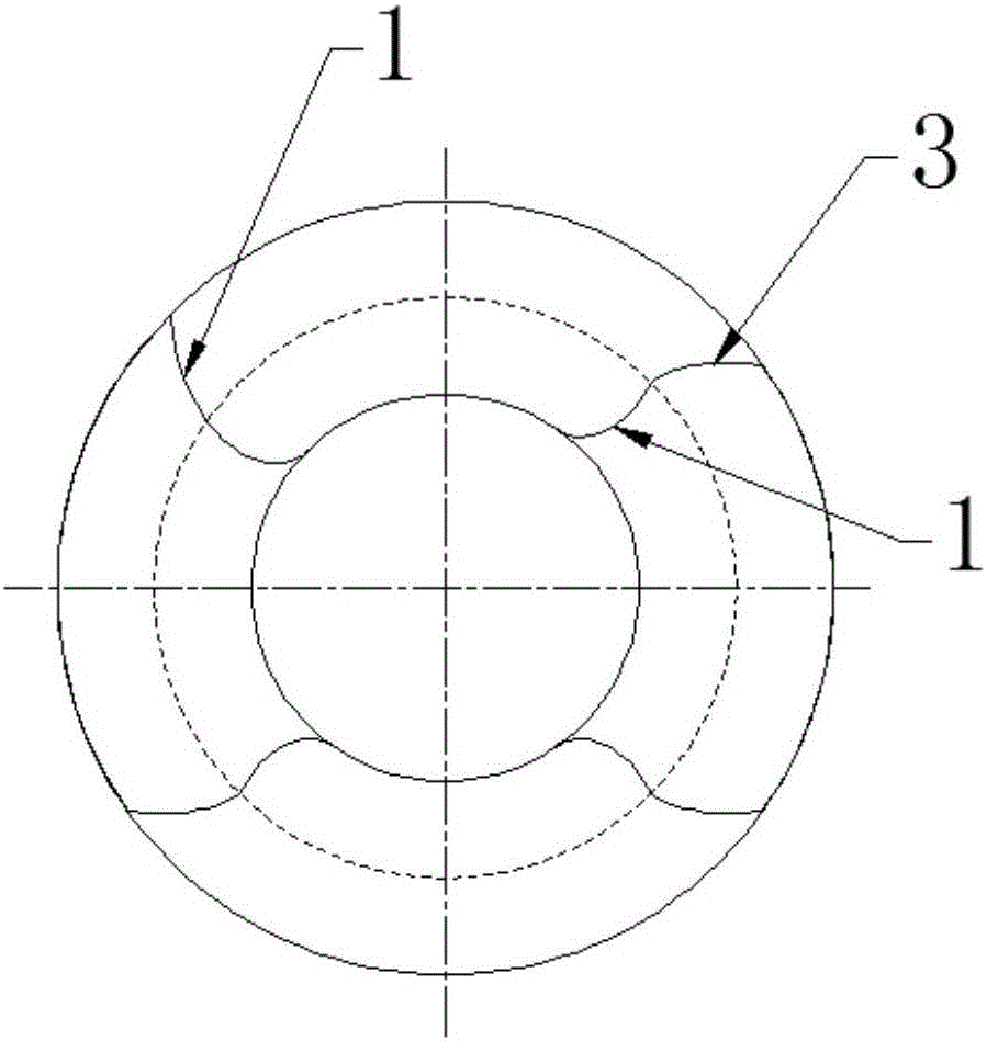
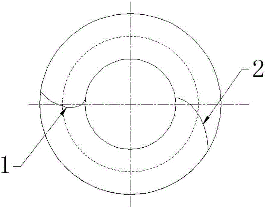
[0054] This embodiment provides an asymmetrical double-ended helical screw that is approximately strictly sealed and has an involute force-transmitting tooth profile.
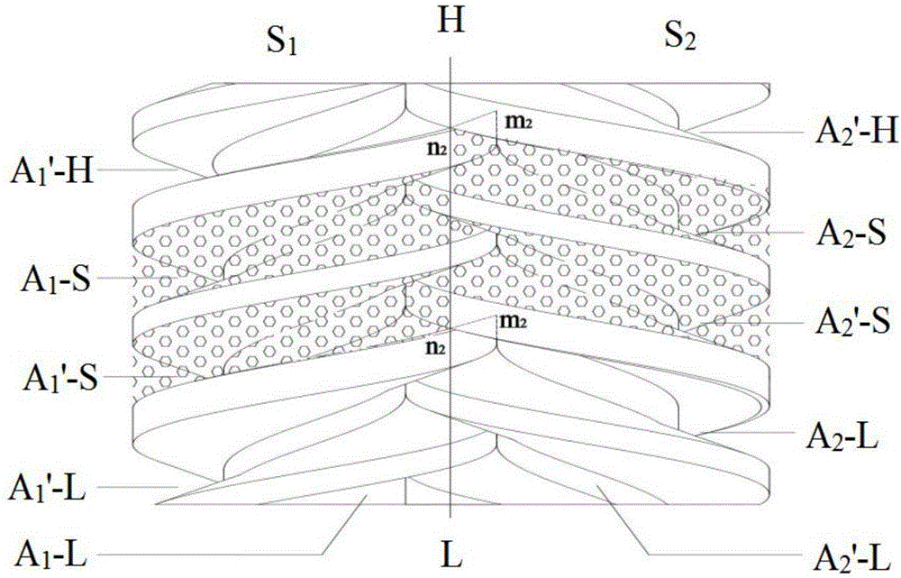
[0055] Such as Figure 5 As shown, the screw in this embodiment has a double-ended helix, and the helix at one end has an asymmetric tooth shape, and the two sides of the tooth shape are respectively the force transmission side bc and the sealing side ae, and the force transmission side bc is an involute tooth Shaped line, the sealing edge ae is an elongated epicycloid toothed line. The helix at the other end of the screw rod in this embodiment is a symmetrical tooth shape, and the two sides of the tooth shape are respectively the force transmission side b'c' and the sealing side b"c", and the force transmission side b'c' and the sealing side b' c' adopts the involute as the tooth profile.
[0056] A twin-screw used in a twin-screw pump, including the active screw S1 and the driven screw S with opposite helic...
Embodiment 2
[0067] On the basis of Example 1, in the screw of the present application, the involute tooth profile used on one side of the helix with asymmetric tooth shape, and the involute tooth used on both sides of the helix with symmetrical tooth shape Among the three involute tooth profile lines in total, at least one involute line has been smoothly corrected at the tooth root section. The smooth correction is a sealed shape, and the correction of the elongated epicycloid can be used, and other forms of correction can also be used. In this example, if Figure 11 As shown, the three involutes are all smooth corrected at the dedendum section, and are corrected by elongated epicycloids. In other embodiments, other combinations can also be used.
[0068] Such as Figure 11 As shown, the screw in this embodiment has a double-ended helix, and the helix at one end has an asymmetric tooth shape, and the two sides of the tooth shape are respectively the force transmission side bc and the se...
Embodiment 3
[0076] On the basis of Example 1, in the screw of the present application, one side of the helix with an asymmetrical tooth shape adopts an elongated epicycloid tooth profile, and the elongated epicycloid is corrected for wear resistance at the top section of the tooth , In this embodiment, cycloidal chamfering is used for correction, and in other embodiments, other forms of correction can also be used.
[0077] Such as Figure 17 As shown, the screw in this embodiment has a double-ended helix, and the helix at one end has an asymmetric tooth shape. Wire. In the sealing edge, the tooth top section is chamfered by an elongated epicycloid ff', and the tooth shape of the sealing edge is composed of an elongated epicycloid section af and an elongated epicycloid chamfering section ff'.
[0078] The main purpose of using the elongated epicycloid ff' chamfer to modify the tooth shape ae of the sealing edge is to improve the wear resistance of the sealing edge, resulting in a gap of...
PUM
 Abstract
Description
Claims
Application Information
 - R&D
- Intellectual Property
- Life Sciences
- Materials
- Tech Scout
- Unparalleled Data Quality
- Higher Quality Content
- 60% Fewer Hallucinations
Browse by: Latest US Patents, China's latest patents, Technical Efficacy Thesaurus, Application Domain, Technology Topic, Popular Technical Reports.
© 2025 PatSnap. All rights reserved.Legal|Privacy policy|Modern Slavery Act Transparency Statement|Sitemap|About US| Contact US: help@patsnap.com


