Air kinetic-energy aircraft lancing device

A ejection device and aircraft technology, applied in the field of aircraft, can solve the problems of reduced bomb load or fuel load, and achieve the effects of high pressure level, improved pressure resistance level, and large energy storage

Active Publication Date: 2016-06-22
杨文清
View PDF9 Cites 0 Cited by
  • Summary
  • Abstract
  • Description
  • Claims
  • Application Information

AI Technical Summary

Problems solved by technology

[0004] The present invention overcomes the deficiencies of the prior art, and provides an embodiment of an aerodynamic aircraft ejection device, hoping to solve the problem that the aircraft on the aircraft carrier can only take off by ski jump, resulting in the reduction of bomb load or fuel load

Method used


Image

  • Air kinetic-energy aircraft lancing device
  • Air kinetic-energy aircraft lancing device
  • Air kinetic-energy aircraft lancing device

Examples


Embodiment 1

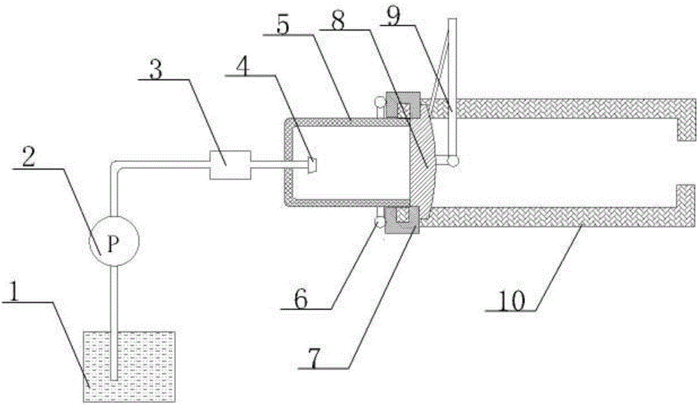
[0030] Such as figure 1 , Figure 3 to Figure 9 As shown, the aerodynamic aircraft ejection device of the present embodiment includes an inflation mechanism and an air storage tank 5, and the inflation mechanism communicates with the air storage tank 5 to provide vaporized gas for the gas storage cylinder, and the inflation mechanism includes a liquefied air storage tank 1, a liquefied air pump 2. Heating jacket 3 and nozzle 4. The liquefied air in the liquefied air storage tank 1 is pumped out by the liquefied air pump and then heated by the heating jacket 3. The heated liquefied air is sprayed and vaporized by the nozzle 4; the opening of the air storage tank 5 A gear-shaped blind plate cover 7 with an inner edge is installed at the port at the end, and a gear-shaped blind plate 8 with a gear-shaped outer edge is installed in the blind plate cover 7. The blind plate cover 7 is connected to the electromagnetic drive device 6, and the electromagnetic drive device 6 has The pr...

Embodiment 2

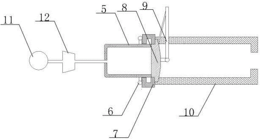
[0035] Such as Figure 2 to Figure 9 As shown, the main structure of the aerodynamic aircraft ejection device of this embodiment is the same as that of Embodiment 1, the difference is that the inflation mechanism is different, so the inflation method of the device of this embodiment is different from that of Embodiment 1, and the air storage tank of this embodiment After a plurality of special-shaped tubes with a trapezoidal cross-section are rolled into the shape of an air storage cylinder, they are surfacing welded in the naturally formed seam, and the lumen of the special-shaped tube is filled with air pressure 20% higher than the preset value of the air storage tank. made of water under pressure. Such as figure 2 , the inflation mechanism includes a motor 11 and an air compressor 12, and the motor 11 drives the air compressor 12 to pump compressed air into the air storage tank 5.

[0036] The workflow of the present embodiment device is:

[0037]The blind plate 8 is pl...


PUM


Abstract

The invention discloses an air kinetic-energy aircraft lancing device.The device comprises an air inflation mechanism and an air storage cylinder, the air inflation mechanism is communicated with the air storage cylinder to provide compressed air for the air storage cylinder, a blind plate sleeve with the inner edge in a gear shape is mounted at an end opening of the open end of the air storage cylinder, a blind plate with the outer edge in a gear shape is mounted in the blind plate sleeve, the blind plate sleeve is connected with an electromagnetic driving device, when detecting that the air pressure in the air storage cylinder reaches a preset value, the electromagnetic driving device drives the blind plate sleeve to rotate by a tooth position, launching rails are further arranged at the end opening of the open end of the air storage cylinder, the shape of the cross section of each launching rail is matched with the shape of the blind plate so that the blind plate can be pushed by the air pressure to perform launch movement in the launching rails, and the blind plate is provided with an aircraft push rod.By means of the device, an aircraft can obtain great launching pushing force, and the problem that only a sliding and leaping launching mode is adopted for an aircraft, so that the bomb load or the oil load is lowered is solved.

Description

technical field [0001] Embodiments of the present invention relate to the technical field of aircraft, and more specifically, embodiments of the present invention relate to an aerodynamic aircraft ejection device. Background technique [0002] At present, the auxiliary take-off device of the aircraft (aircraft) on the short runway, especially the aircraft carrier, only has the steam catapult device that the United States has applied on the aircraft carrier and the electromagnetic catapult device that is still in the research and development stage. However, in order to maintain its military advantage, the United States has implemented a technical blockade, so almost all aircraft carriers except the United States can only use the ski jump take-off method, and the ski-jump take-off will be reduced by one-third compared with the catapult take-off The amount of bombs or fuel carried by the aircraft carrier will greatly reduce the effectiveness of the aircraft carrier. [0003] I...

Claims


Application Information

Patent Timeline
Patent Type & Authority Applications(China)
IPC IPC(8): F17C5/06F17C7/04F17C13/02F17C13/04
CPCF17C5/06F17C7/04F17C13/025F17C13/04F17C2223/0123F17C2225/0123F17C2265/066
Inventor 杨文清
Owner 杨文清
Why Eureka
Try Eureka