Combined type distributed optical fiber sensing method and system integrated with chaotic light source and coherent detection

A technology of distributed optical fiber and sensing method, which is applied in the direction of testing optical fiber/optical waveguide equipment, optical instrument testing, and reflectometers for detecting backscattered light in the time domain. Too ideal, resolution limitations and other issues

Active Publication Date: 2016-06-22
NANJING XIAOZHUANG UNIV
View PDF6 Cites 12 Cited by
  • Summary
  • Abstract
  • Description
  • Claims
  • Application Information

AI Technical Summary

Problems solved by technology

The disadvantage of this technology is that its resolution is limited by the width of the light pulse, and its sensing distance is limited by the power of the detection light pulse. Resolution and sensing distance are a pair of contradictions in this technology, and it is difficult to have both
In recent years, some research units have proposed the measurement method of optical time domain ref

Method used


Image

  • Combined type distributed optical fiber sensing method and system integrated with chaotic light source and coherent detection
  • Combined type distributed optical fiber sensing method and system integrated with chaotic light source and coherent detection
  • Combined type distributed optical fiber sensing method and system integrated with chaotic light source and coherent detection

Examples


Example Embodiment

[0036] The preferred embodiments of the present invention will be described in detail below with reference to the accompanying drawings.

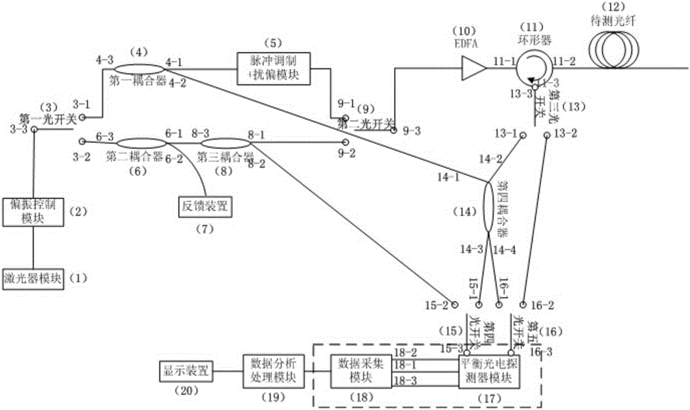
[0037] The compound distributed optical fiber sensing system fusing chaotic light source and coherent detection of the present invention, its preferred specific implementation is as follows figure 1 As shown, it includes a laser module (1), a polarization control module (2), a first optical switch (3), a first coupler (4), a pulse modulation scrambling polarization module (5), and a second coupler (6) , Feedback device (7), third coupler (8), second optical switch (9), optical amplifier (10), circulator (11), optical fiber (12), third optical switch (13), fourth Coupler (14), fourth optical switch (15), fifth optical switch (16), balanced photodetector module (17), data acquisition module (18), data analysis and processing module (19), display module (20) ).

[0038] In the figure, 3-1 to 3-3 are the input and output ports of the first optica...


PUM


Abstract

A combined type distributed optical fiber sensing system integrated with chaotic light source and coherent detection is disclosed and comprises a laser module, a polarization control module, a first optical switch, a first coupler, a pulse modulation and polarization scrambling module, a second coupler, a feedback device, a third coupler, a second optical switch, an EDFA light amplifier, a circulator, an optical fiber, a third optical switch, a fourth coupler, a fourth optical switch, a fifth optical switch, a balance photoelectric detector, a data collecting module, a data analyzing and processing module and a display device, wherein a coherent light time domain reflectometer or a chaotic light time domain reflectometer is chosen to be used in the system according to monitoring needs; by switching optical switch combinations, the coherent light time domain reflectometer or the chaotic light time domain reflectometer can be obtained. The beneficial effects of the combined type distributed optical fiber sensing method and system are that most of measuring devices in the system are employed by two measuring solution, the utilization efficiency of the sensing devices is improved, and system links are jointly monitored by the two measuring solutions; the detection sensitivity, the sensing distance and the positioning precision of the system can be optimized.

Description

technical field [0001] The invention relates to an optical fiber sensing method and system, in particular to a composite distributed optical fiber sensing method and system combining chaotic light source and coherent detection. Background technique [0002] Optical Time Domain Reflectometer (OTDR) uses backscattering / reflection signals to monitor fault points in optical fiber links. Measurement, and can feed back the location information of the corresponding fault point, has a wide range of research and applications in academic research, industrial production and social life, and plays an important role in the optical fiber communication and optical fiber sensing industries. [0003] The traditional OTDR technology usually emits a detection light pulse at the light source end, and obtains the distance information of the fault point and parameter information such as loss and strain by monitoring the power of the reflected / scattered optical signal back to the detection end. T...

Claims


Application Information

Patent Timeline
IPC IPC(8): G01M11/00
CPCG01M11/3118
Inventor 陈勐勐颜森林
Owner NANJING XIAOZHUANG UNIV
Why Eureka
Try Eureka