Voltage regulator

A voltage regulator and regulating tube technology, applied in the field of electronics, can solve the problem of slow response speed of the voltage regulator

Active Publication Date: 2016-06-22
SHANGHAI HUAHONG GRACE SEMICON MFG CORP
View PDF5 Cites 2 Cited by
  • Summary
  • Abstract
  • Description
  • Claims
  • Application Information

AI Technical Summary

Problems solved by technology

[0004] Conventional voltage regulators suffer from slow response

Method used


Image

  • Voltage regulator
  • Voltage regulator

Examples


Embodiment Construction

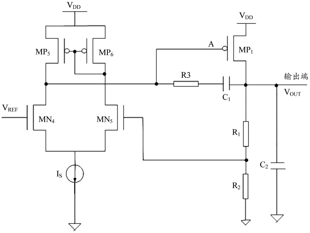
[0024] refer to figure 1 , a schematic diagram of the structure of an existing voltage regulator is given.

[0025] The error amplifier consists of a PMOS tube MP 5 , PMOS tube MP 6 , NMOS tube MN 4 , NMOS tube MN 5 and a bias current source I S constitute. MP 5 source of the voltage source V DD coupling, gate to MP 6 The gate is coupled, the drain is connected to the MN 4 The drain and pass tube MP 1 Gate coupling; MP 6 source of the voltage source V DD coupling, gate to drain coupling, drain to MN 5 Drain coupling; MN 4 The gate is connected to the reference voltage V REF , source and bias current source I S The input terminal coupling; MN 5 The gate and the first sampling resistor R 1 The second terminal and the second sampling resistor R 2 The first end of the coupling, source and bias current source I S The input terminal is coupled. Bias Current Source I S The output terminal is coupled to the ground.

[0026] Adjustment tube MP 1 It is a PMOS tube...


PUM


Abstract

A voltage regulator comprises an error amplifier, a second discharge channel and a regulating pipe. The error amplifier comprises a first discharge channel and a bias power source, wherein the first discharge channel is coupled between the control end of the regulating pipe and a ground wire, and the discharge current of the first discharge channel is not larger than the maximum output current of the bias power source. The input end of the regulating pipe is coupled with a preset voltage source, the output end of the regulating pipe is coupled with the output end of the voltage regulator, the control end of the regulating pipe is coupled with the input end of the first discharge channel and the input end of the second discharge channel, and the potential of the control end and the voltage of the output end of the voltage regulator change in the same direction. The second discharge channel is coupled between the control end of the regulating pipe and the ground wire. The sum of the discharge current of the first discharge channel and the discharge current of the second discharge channel and the potential of the control end of the regulating pipe change in opposite directions. The voltage regulator has high response speed.

Description

technical field [0001] The invention relates to the field of electronics, in particular to a voltage regulator. Background technique [0002] With the development of electronic technology, the application of voltage regulator is more and more extensive. For example, many analog circuits, radio frequency circuits, memory circuits, and a system on a chip (System OnaChip, SoC), etc. [0003] In practical applications, when the load current changes, it is usually required that the voltage regulator can provide a faster response speed. In a traditional voltage regulator, when the load current changes suddenly, the voltage regulator usually responds by charging and discharging the capacitor with the bias current, and the response time depends on the charging and discharging speed of the capacitor with the bias current. [0004] Conventional voltage regulators suffer from slow response. Contents of the invention [0005] The technical problem solved by the invention is how to ...

Claims


Application Information

Patent Timeline
Patent Type & Authority Applications(China)
IPC IPC(8): G05F1/625
CPCG05F1/625
Inventor 徐光磊
Owner SHANGHAI HUAHONG GRACE SEMICON MFG CORP
Why Eureka
Try Eureka