System and method for white balance control of LED display screen

A technology of LED display and control system, applied in the direction of static indicators, instruments, etc., can solve the problems of working voltage difference, color cast of display module, etc., and achieve the effect of avoiding the change of resistance value

Active Publication Date: 2018-07-20
SHENZHEN ABSEN OPTOELECTRONIC CO LTD +1
View PDF7 Cites 0 Cited by
  • Summary
  • Abstract
  • Description
  • Claims
  • Application Information

AI Technical Summary

Problems solved by technology

[0005] The main purpose of the present invention is to provide a LED display screen white balance control system and method, aiming to overcome the problems existing in the background technology, and at the same time realize the rapid white balance configuration of the LED module, the cabinet and the entire display screen, and overcome the problems in the later stages. Due to the temperature difference and working voltage difference between the display modules during operation, the color cast problem at the display module level is caused, and the intelligent white balance compensation and correction can be realized

Method used


Image

  • System and method for white balance control of LED display screen
  • System and method for white balance control of LED display screen
  • System and method for white balance control of LED display screen

Examples


Embodiment 1

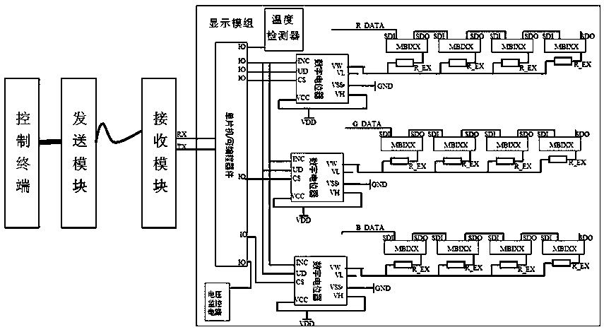
[0033] refer to figure 1 , 2 , 3 is a schematic diagram of the structure of this embodiment. Among them, such as figure 1 As shown, the LED display screen white balance control system of the present invention is composed of a control terminal, a sending module, a receiving module and an LED module.

[0034] Each pixel on the LED module consists of red, green, and blue lights. The red, green, and blue lights of each pixel can be installed on the light board separately, or they can be packaged together and installed. There is a microprocessor and several digital potentiometers in the LED module. The number of digital potentiometers can be determined according to actual needs. In the preferred solution, the number of digital potentiometers is 3, that is, one digital potentiometer corresponds to a driver IC of a color lamp bead. One end of the digital potentiometer is electrically connected to the current adjustment pin of the driving IC of the same color lamp bead, and the o...

Embodiment 2

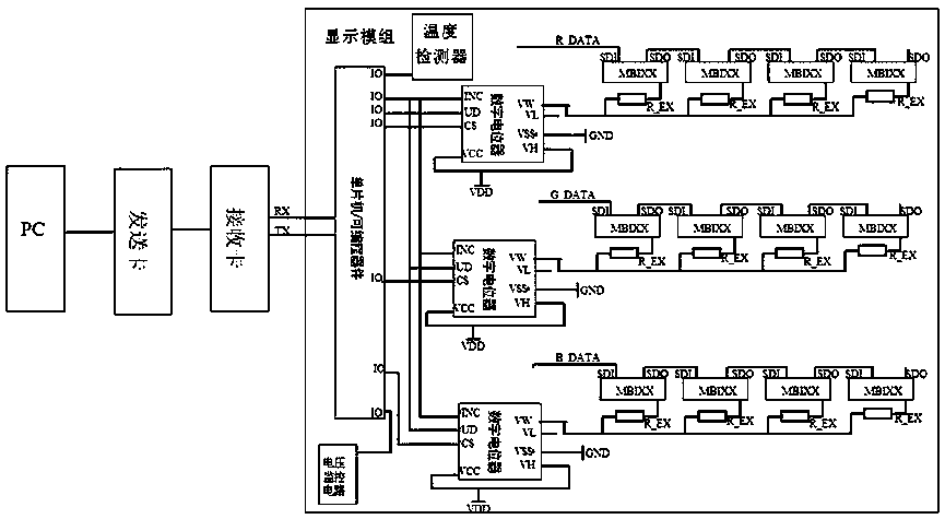
[0038] refer to Figure 4 It is another improved embodiment of the present invention. Wherein, the control terminal is a mobile phone, the sending module is a wireless sending module in the prior art such as a Bluetooth or RFID module, and the receiving module is a wireless receiving module in the prior art such as a Bluetooth or RFID module. Because most smart phones have a light sensing module, through which the brightness of ambient light is read. However, the white balance control system of the LED display screen of the present invention can cleverly utilize its light sensing module to perform rapid initial configuration and configuration correction of the white balance of the LED display module and the LED display screen. During the quick initialization configuration process, the white balance configuration program or software is an APP installed on the mobile phone. The APP has the authority to obtain the data collected by the optical sensor module of the mobile phone ...

Embodiment 3

[0041] refer to Figure 5 , is a further optimization carried out according to Embodiment 1 and Embodiment 2. As shown in the figure, the LED module has a serial port cascading module (not shown in the figure), and each LED module is cascaded through the serial port cascading module. Since the LED module has a microprocessor such as a single-chip microcomputer, the LED module is cascaded through the serial port, and data communication becomes simple and convenient. The LED module includes a main control LED module and a controlled LED module. The main control LED module is directly electrically connected to the receiving module to receive configuration instructions and data from the control terminal; The main control LED module obtains and executes configuration instructions and data from the control terminal and transmits them to the next level. The controlled LED module collects the temperature and voltage values ​​obtained by its microprocessor to the main control LED modu...


PUM


Abstract

The invention discloses a white balance control system and method for an LED display screen. The system is composed of a control terminal, a sending module, a receiving module and an LED module group. A microprocessor and a plurality of digital potentiometers are arranged inside the LED module group; and one end of each digital potentiometer is connected with a drive IC current adjusting pin of a lamp bead with a same color electrically and the other end is connected with the microprocessor electrically. The control terminal is used for calculating resistance values of the digital potentiometers corresponding to LED drive chips of a red light, a green light, and a blue light and generating a configuration instruction and data, and then the configuration instruction and the data are transmitted to the receiving module by the sending module. The microprocessor is used for executing the configuration instruction from the control terminal, generating a control signal corresponding to the configuration instruction, and outputting the control signal to all digital potentiometers, so that resistances of all digital potentiometer are adjusted to be corresponding target values. According to the invention, initial configuration of white balance can be carried out rapidly; and a problem that currents of the drive IC and LED change frequently due to changing of a resistance value of a thermistor and thus white balance compensation can not be carried out correctly or normal displaying of the LED display screen is affected directly can be solved.

Description

technical field [0001] The invention relates to the technical field of LED display screens, in particular to a white balance control system and method for LED display screens. Background technique [0002] At present, in the display industry, LED brightness is achieved by changing the current flowing through the LED. There are two ways to change the LED current. One is to change the output PWM pulse width of the driver chip, and the other is to adjust the driver chip. The output white balance resistor is realized. [0003] For example: Chinese patent 201420476311.0 LED display automatic white balance brightness adjustment structure, which uses a spectrometer as brightness collection, and controls the PWM chip through the calculation of the host computer, and then changes the current of each LED chip to automatically adjust the white balance. The problem is: repeated detection and feedback are required, and then the PWM chip is continuously controlled to complete the white b...

Claims


Application Information

Patent Timeline
Patent Type & Authority Patents(China)
IPC IPC(8): G09G3/32
CPCG09G3/32
Inventor 焦方
Owner SHENZHEN ABSEN OPTOELECTRONIC CO LTD
Why Eureka
Try Eureka