Driving system and driving method of planar organic electroluminescent device

A driving system and luminescent technology, applied in electroluminescent light sources, electric light sources, lighting devices, etc., can solve the problems of the light emitting device 100 being uncut, high cost, and long production cycle, so as to achieve good luminous efficiency and avoid electric shock Effect

Active Publication Date: 2019-05-14
IND TECH RES INST
View PDF4 Cites 0 Cited by
  • Summary
  • Abstract
  • Description
  • Claims
  • Application Information

AI Technical Summary

Problems solved by technology

[0008] In this way, the luminous efficiency of the light-emitting device 100 is likely to deteriorate due to failure of one of the organic electroluminescent elements 110A- 110C.
[0009] In addition, in the existing light-emitting device 100, since a plurality of organic electroluminescent elements 110A-110C are connected in series, high-voltage driving is required, which may cause hidden dangers of electric shock.
[0010] In addition, if figure 1 The light emitting device 100 shown is non-cuttable
Any form of cutting may damage the electrical connections of the organic electroluminescent elements 110A- 110C, resulting in poor luminous efficiency of the light emitting device 100
Furthermore, when a light-emitting device 100 with a set area is required, it must be ordered in advance from the manufacturer, which not only has high cost, but also has a long production cycle.

Method used


Image

  • Driving system and driving method of planar organic electroluminescent device
  • Driving system and driving method of planar organic electroluminescent device
  • Driving system and driving method of planar organic electroluminescent device

Examples


Embodiment Construction

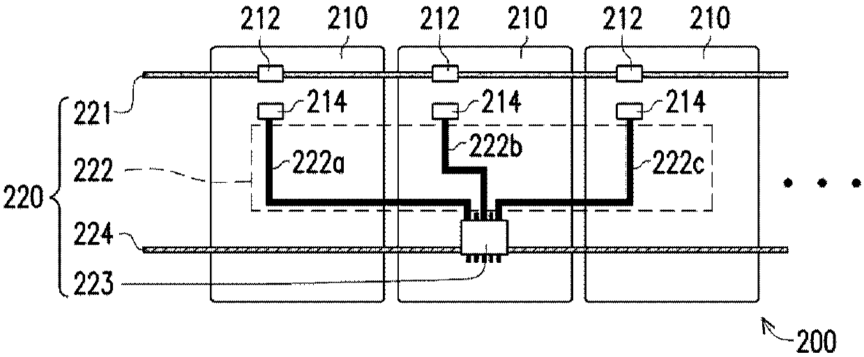
[0079] figure 2 It is a schematic diagram of a planar organic electroluminescent device and a driving system of the planar organic electroluminescent device according to an embodiment of the present invention. Please refer to figure 2 , the planar organic electroluminescent device 200 may have a plurality of light emitting elements 210 , and each light emitting element 210 has a first electrode 212 and a second electrode 214 . The first electrode 212 can be an anode (+) for inputting holes, and the second electrode 214 can be a cathode (−) for inputting electrons. Electrons and holes are combined in the light-emitting layer of the light-emitting element 210 to emit light. The light emitting element 210 may be an organic electroluminescence element. When the light-emitting element 210 uses an organic electroluminescent element, it can be fabricated in a large area, and has flexibility and cutability.

[0080] please refer again figure 2 , the driving system 220 of the p...


PUM


Abstract

The invention provides a driving system and a driving method of a planar organic electroluminescent device. Wherein, the light emitting device has a plurality of light emitting elements, and each light emitting element has a first electrode and a second electrode. The driving system of the light emitting device includes: a first circuit, a second circuit, a driving module and a grounding circuit. The first line is connected to the first electrode of each light-emitting element, and the first line provides a constant voltage to each light-emitting element. The second line is connected to the second electrode of each light emitting element. The driving module is respectively connected to the second electrode of each light-emitting element via the second line. The grounding circuit is connected to the driving module, and the grounding circuit grounds each light-emitting element, wherein the first electrodes of the plurality of light-emitting elements are connected to each other, and the plurality of light-emitting elements are driven by a constant current output by the driving module. The driving system of the light-emitting device enables the light-emitting device to be cut in any area and shape, and the driving current of the cut light-emitting device can be automatically adjusted with the chip resistor.

Description

technical field [0001] The invention relates to a driving system and a driving method, in particular to a driving system and a driving method of a planar organic electroluminescence device. Background technique [0002] Compared with traditional lighting sources, such as incandescent lamps and fluorescent lamps, LED light sources and Organic Light Emitting Diode light sources (Organic Light Emitting Diode light sources, OLED light sources) are thin, mercury-free, and UV-free. Because of the advantages of planar light source, it is regarded as a new light source with great potential. [0003] figure 1 It is a conventional light-emitting device using a plurality of organic electroluminescent elements. Please refer to figure 1 , the light-emitting device 100 includes: a plurality of organic electroluminescent elements 110A to 110C ( figure 1 Only 3 are shown in), a plurality of connecting circuit boards 120 ( figure 1 Only 3 are shown in ), the power line 130 and the groun...

Claims


Application Information

Patent Timeline
Patent Type & Authority Patents(China)
IPC IPC(8): H05B33/08H05B33/26H05B44/00
CPCH05B33/26H05B45/60Y02B20/30H10K59/00H10K50/814H10K50/824H10K59/18
Inventor 林轩宇蔡承延廖书辰
Owner IND TECH RES INST
Why Eureka
Try Eureka