
Top light-emitting device

A top-emitting device technology, applied in the field of top-emitting devices, can solve the problems of difficult modulation of white light, few lighting fields, and limited substrate selection range, etc., to achieve the effect of eliminating microcavity effect, high device luminous efficiency, and simple process

Inactive Publication Date: 2016-06-22
BEIJING VISIONOX TECH
View PDF3 Cites 2 Cited by
  • Summary
  • Abstract
  • Description
  • Claims
  • Application Information

AI Technical Summary

Problems solved by technology

The substrate used for bottom-emitting OLED devices must be transparent, which greatly limits the choice of substrates
Some substrates with excellent performance, such as metal foil substrates with good heat dissipation and high mechanical strength, can be used as flexible substrates. Due to their opacity, such substrates cannot be used for bottom-emitting devices for lighting, and can only be used for top-emitting device
However, the traditional top-emitting OLED device is not easy to modulate white light due to the microcavity effect, so it is rarely used in the field of lighting

Method used


Image

  • Top light-emitting device

Examples


Embodiment Construction

[0017] The present invention will be further described below in conjunction with the accompanying drawings and specific embodiments, so that those skilled in the art can better understand the present invention and implement it, but the examples given are not intended to limit the present invention.

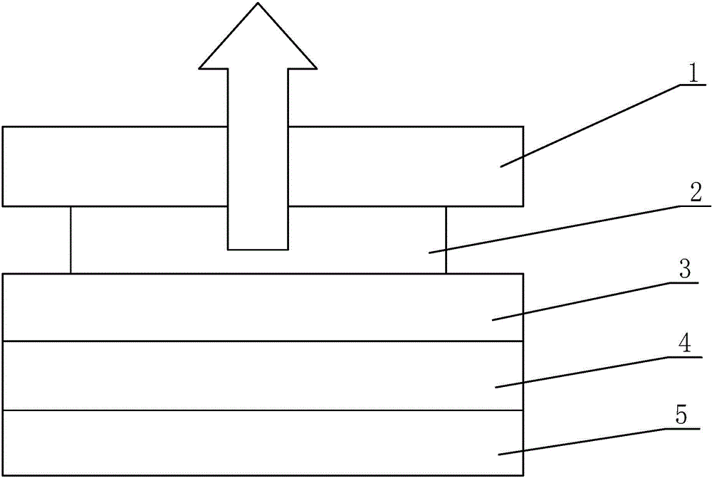
[0018] Such as figure 1 As shown, the top-emitting device of the present invention includes a substrate, a transparent conductive layer, an organic light-emitting layer and a cathode layer, and a high diffuse reflection layer is also provided between the substrate and the transparent conductive layer. Wherein, the high diffuse reflection layer is located on the surface of the substrate, and the transparent conductive layer is located on the high diffuse reflection layer. The high diffuse reflection layer refers to a reflective layer with a reflectivity of greater than 80% for visible light, preferably a reflective layer with a reflectivity of greater than 95% for visible light.

...


PUM


Abstract

The invention discloses a top light-emitting device. The top light-emitting device comprises a substrate, a transparent conductive layer, an organic light emitting layer and a cathode layer; a high-diffusion reflection layer is arranged between the substrate and the transparent conductive layer; and the reflectivity of the high-diffusion reflection layer for visible light is larger than 8%. According to the top light-emitting device of the invention, the high-diffusion reflection layer is arranged between the substrate and the transparent conductive layer, so that the micro cavity effect of a traditional top light-emitting device can be eliminated, and therefore, white light can be obtained through modulation and can be used for lighting and the top light-emitting device of the invention has the advantages of simple process and high luminous efficiency.

Description

technical field [0001] The invention relates to the technical field of OLEDs, in particular to a top-emitting device. Background technique [0002] In the technical field of OLED (Organic Light-Emitting Diode, organic light-emitting diode), the device structure generally includes a bottom-emitting device and a top-emitting device. The substrate used in bottom-emitting OLED devices must be transparent, which greatly limits the range of substrate choices. Some substrates with excellent performance, such as metal foil substrates with good heat dissipation and high mechanical strength, can be used as flexible substrates. Due to their opacity, such substrates cannot be used for bottom-emitting devices for lighting, and can only be used for top-emitting device. However, due to the microcavity effect, traditional top-emitting OLED devices are not easy to modulate white light, so they are rarely used in the field of lighting. Contents of the invention [0003] The technical pro...

Claims


Application Information

Patent Timeline
IPC IPC(8): H01L51/52H01L51/54
Inventor 朱映光张国辉王静董艳波宋沛
Owner BEIJING VISIONOX TECH
Learn More