Conductor molding device and method

A kind of wire, one-sided technology, applied in the direction of electromechanical devices, the shape/style/structure of winding conductors, the manufacture of motor generators, etc., can solve the problems of poor forming accuracy and poor forming accuracy

Active Publication Date: 2016-06-22
AISIN AW CO LTD +1
View PDF10 Cites 11 Cited by
  • Summary
  • Abstract
  • Description
  • Claims
  • Application Information

AI Technical Summary

Problems solved by technology

Therefore, there is a fear that the lead part is dragged and deformed by the die due to friction between the lead part and the die when the forming dies are separated from each other, thereby deteriorating the forming accuracy.
In addition, not only for a lead wire having a rectangular (rectangular) cross section, but also for a lead wire having a square, circular, or elliptical cross section, a pair of molding dies are used to perform bending processing toward the first bending direction and a direction that is aligned with the second bending direction. In the case of bending in the second bending direction perpendicular to the first bending direction, such a deterioration in molding accuracy may also occur.

Method used


Image

  • Conductor molding device and method
  • Conductor molding device and method
  • Conductor molding device and method

Examples


Embodiment Construction

[0049] Next, modes for implementing the present invention will be described with reference to the drawings.

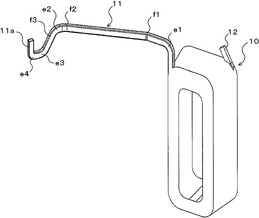
[0050] figure 1 It is a perspective view showing the coil 10 formed by the coil end shaping|molding apparatus which is a wire shaping|molding apparatus of this invention. The coil 10 shown in this figure is included in a stator (not shown) for a motor, and the stator for a motor is configured together with a rotor not shown, and is used as a driving source and / or a generator of an electric vehicle or a hybrid vehicle, for example. three-phase AC motors. In addition, the motor stator includes a plurality of coils 10 and a not-shown stator core. The stator core has: a plurality of split cores arranged in an annular shape; and a fixing ring for fixing the plurality of split cores. Each coil 10 is attached to a corresponding split iron core via an insulating member (not shown), and the motor stator (stator iron core) is covered with molding resin such as thermosetting re...


PUM


Abstract

The invention provides a conductor molding device and method. A coil-end molding device (20) includes a first molding die (21) and a second molding die (22) which approach each other along an X-direction and mold an edgewise bend part and a flatwise bend part on a lead wire part (11), and a third molding die (23) which approaches the second molding die (22) along the X-direction and molds an edgewise bend part in coordination with the second molding die (22) on a loose end section of the lead wire part (11). The second molding die (22) is configured so as to be capable of moving towards and away from the first molding die (21) along a Y-direction which differs from the X-direction, and the third molding die (23) is configured so as to be capable of moving towards and away from the second molding die (22) along the Y-direction which differs from the X-direction.

Description

technical field [0001] The present invention relates to a wire forming device and method for forming a first bending portion bent in a first bending direction and a second bending portion bent in a second bending direction perpendicular to the first bending direction for a wire. Background technique [0002] Conventionally, as a coil constituting a stator of a rotating electric machine, a coil formed by winding a wire material (flat wire) having a rectangular cross section and having a lead portion (lead wire) at one end is known (for example, refer to Patent Document 1). The coil is attached to the stator core via an insulating member, and the end of the lead is electrically connected to the end of the corresponding other coil on the opposite side to the lead. In addition, as coils of rotating electrical machines, coils formed by inserting approximately U-shaped conductors, that is, conductor segments, into slots formed in stator cores and rotor cores and welding the conduc...

Claims


Application Information

Patent Timeline
Patent Type & Authority Applications(China)
IPC IPC(8): H02K15/04
CPCH02K15/04B21F1/004H02K3/28
Inventor 桥本伸吾伊藤克也太田贵宪松尾大辅五十岚未来赤尾宪彦川浦弘贵小林央幸杉浦宏春
Owner AISIN AW CO LTD
Why Eureka
Try Eureka