Modified shell punching die

A technology for stamping dies and shells, which is applied in the field of improved shell stamping dies, which can solve the problems of cumbersome procedures, troublesome people, difficult shell edge reverse-wrapping stamping and forming, etc.

Inactive Publication Date: 2016-06-29
FUJIAN HUAKE MOLD TECH
View PDF10 Cites 2 Cited by
  • Summary
  • Abstract
  • Description
  • Claims
  • Application Information

AI Technical Summary

Problems solved by technology

This invention patent is mainly used for the stamping and forming of mobile phone shells. The above two invention patents are like other common stamping dies on the market. The structural principles are roughly the same, so the functions and effects

Method used


Image

  • Modified shell punching die
  • Modified shell punching die
  • Modified shell punching die

Examples


Embodiment Construction

[0058] In order to further explain the technical solutions of the present invention, specific examples are given below to illustrate in detail.

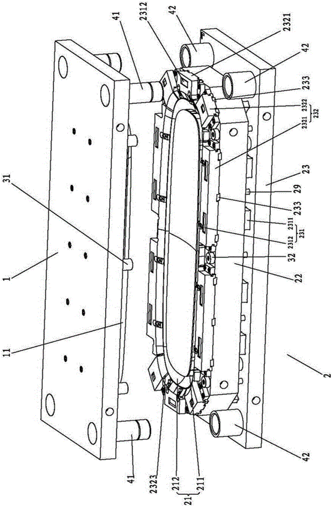
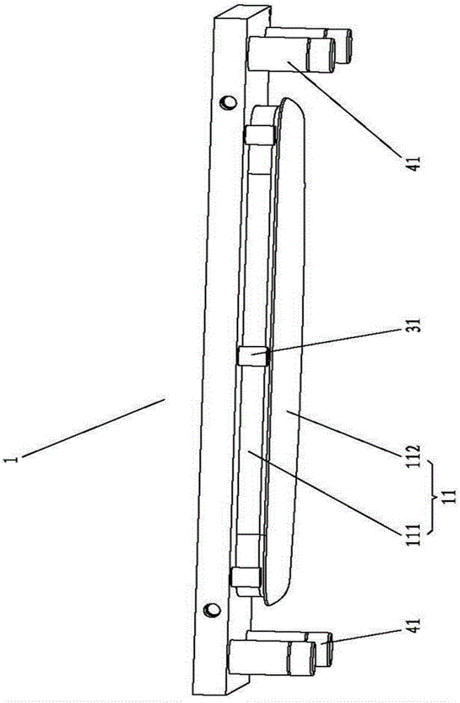
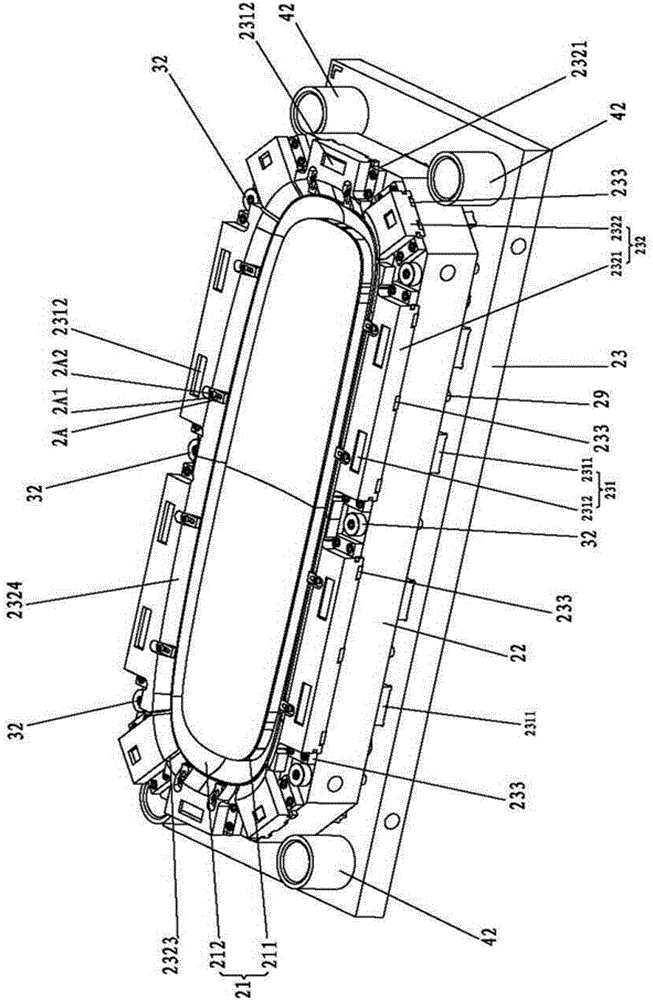
[0059] A stamping die of a shell of the present invention, such as Figure 1-12 As shown, it includes an upper mold 1 at the top and a lower mold 2 at the bottom. The upper die 1 has a punch 11 facing downward, and the lower die 2 has a die 21 with an opening facing upward. The specific structure can be that the inner surface of the die 21 is covered with a soft rubber layer, which can prevent the die 21 from scratching the shell The lower mold 2 includes the first layer, the second layer, the third layer and the fourth layer from top to bottom; As the mold wall block 212 of the cavity wall of the concave mold 21 outside the bottom block 211, the mold bottom block 211 constitutes the first layer, the mold wall block 212 has a mold wall bottom plate 2121 blocked at the lower end, the mold wall block 212 and the mold wall bottom plate...


PUM


Abstract

The invention provides a modified shell punching die. A shell blank is laid on the upper surface of a die bottom block, positioned and heated to be softened, an upper die body punches downwards, a puncher pin drives the die bottom block to move downwards at first, when the die bottom block makes contact with a die wall bottom plate, the die bottom block exactly fits with die wall blocks, and the die bottom block and the die wall blocks are spliced into a complete female die. The puncher pin abuts against a first layer and a second layer to continue to move downwards so as to compress first springs and second springs, and turnup edges of the shell blank are formed; when the puncher pin decreases to a certain degree, the die wall bottom plate pushes a die frame bottom plate to drive a die frame block to move downwards along a vertical block, the die frame block drives a sliding block to move downwards by the aid of an inclined block, and meanwhile, the sliding block moves inwards through a guide rail by the aid of inward horizontal thrust of the inclined block; and when a slender neck part corresponds to the sliding block, the turnup edges of the shell blank are ejected into the slender neck part through the sliding block by means of a step between an end socket and the slender neck part, and reverse coating edges are formed. The modified shell punching die can smoothly and efficiently form the reverse coating edges of a shell, and is novel and reasonable in structure and high in practicability.

Description

[0001] This case is 201410556095.5, a divisional application titled "a stamping die for a shell", and the filing date of the parent case is 2014.10.20. technical field [0002] The present invention relates to an improved shell stamping die. Background technique [0003] The structure of the stamping die is known, such as Chinese invention patent CN201110091962.9 discloses a stamping die, including: base, several guide rods, lower die, upper die, platform pressure head, top plate, connecting block, guide rod and lower die set On the base, the upper mold is set on the lower mold, and the upper mold and the lower mold are respectively provided with material cavities. In the rod hole, the connecting block is set on the top of the top plate, the platform pressure head is set under the top plate and its shape matches the pressure head hole, and the pads and adjustment pieces are arranged in turn between the top plate and the platform pressure head. A guide sleeve is arranged in ...

Claims


Application Information

Patent Timeline
IPC IPC(8): B21D37/12
CPCB21D37/12
Inventor 钱建根李小育
Owner FUJIAN HUAKE MOLD TECH
Why Eureka
Try Eureka