Casting method for compression impeller

A technology of pressing impeller and casting mold, applied in casting molding equipment, casting mold, casting mold composition, etc., can solve the problems of high mold production cost, low production efficiency, difficult mold disassembly, etc., to reduce production cost and improve production efficiency. , The effect of improving the speed of disassembly and assembly

Active Publication Date: 2016-06-29
GRIMAT ENG INST CO LTD
View PDF9 Cites 2 Cited by
  • Summary
  • Abstract
  • Description
  • Claims
  • Application Information

AI Technical Summary

Problems solved by technology

Therefore, it is difficult to design the mold structure and the cost of mold production is high.
Especially for metal molds (such as semi-solid die-casting molds), since the blades are curved surfaces, automatic mold opening and closing cannot be realized, resulting in difficulty in mold disassembly and low production efficiency

Method used


Image

  • Casting method for compression impeller
  • Casting method for compression impeller

Examples


Embodiment 1

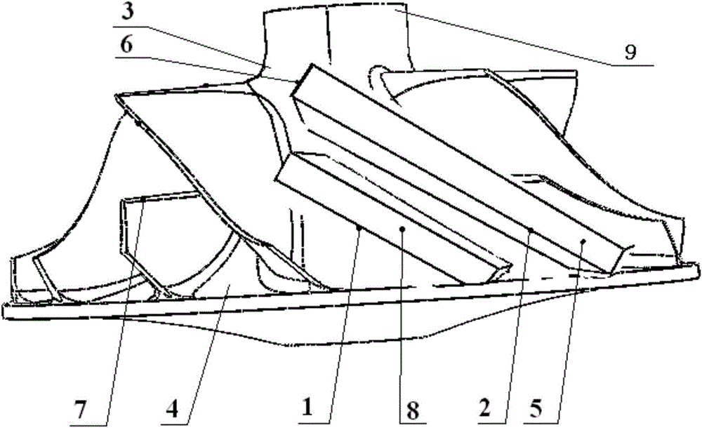
[0027] The angle between the upper edge plane 6 of the primary primary blade and the central axis 9 of the impeller is equal to 90 degrees; the angle between the upper edge plane 7 of the initial secondary blade and the central axis 9 of the impeller is equal to 90 degrees.

[0028] The upper and lower surfaces of the initial primary blade 2 and the initial secondary blade 1 of the impeller casting mold are parallel to each other, and the distance between the initial primary blade and the initial secondary blade is 5mm. The mold can be ejected synchronously in the same direction to realize automatic mold opening and closing.

Embodiment 2

[0030] The angle between the outer edge plane 5 of the primary primary blade and the central axis 9 of the impeller is equal to 95 degrees; the angle between the outer edge plane 8 of the initial secondary blade and the central axis 9 of the impeller is equal to 95 degrees.

[0031] The upper and lower surfaces of the initial primary blade 2 and the initial secondary blade 1 of the impeller casting mold are parallel to each other, and the distance between the initial primary blade and the initial secondary blade is 5mm. The mold can be ejected synchronously in the same direction to realize automatic mold opening and closing.

Embodiment 3

[0033] The angle between the upper edge plane 6 of the primary primary blade and the central axis 9 of the impeller is equal to 100 degrees; the angle between the upper edge plane 7 of the initial secondary blade and the central axis 9 of the impeller is equal to 100 degrees.

[0034] The distance between the initial primary blade and the initial secondary blade is constant from the inlet of the impeller to the outlet of the impeller. The radial distance between the lower surface of the initial primary blade 2 and the upper surface of the adjacent primary secondary blade 1 along the central axis 9 of the impeller becomes larger, and the angle between the two planes is 7 degrees.

[0035] The radial distance between the upper surface of the initial primary blade of the impeller casting mold and the upper surface of the adjacent initial secondary blade along the central axis 9 of the impeller becomes larger, and the angle between the two planes is 9 degrees.

[0036] The linear ...


PUM


Abstract

The invention belongs to the technical field of complex part forming, and relates to a casting method for a compression impeller. According to the casting method for the compression impeller, when a compression impeller casting die is manufactured, the size of a compression impeller product is regarded as the datum; each primary blade of the compression impeller casting die is a hexahedron which can accommodate a primary blade of the compression impeller product, and the upper surface, the lower surface and the marginal surface which is not combined with a compression impeller hub of each primary blade are all planes. Each secondary blade of the compression impeller casting die is a hexahedron which can accommodate a secondary blade of the compression impeller product, and the upper surface, the lower surface and the marginal surface which is not combined with a compression impeller hub of each secondary blade are all planes. The follow-up machining amount of a compression impeller casting obtained through the casting method for the compression impeller is far smaller than that of a compression impeller rotating body which is directly formed through forging, automatic die releasing of the die can be achieved, and on the premise of guaranteeing the excellent performance, the follow-up machining amount and machining cost are lowered.

Description

technical field [0001] The invention belongs to the technical field of complex component forming, and relates to a casting method of a near-pressure impeller. Background technique [0002] Turbochargers are widely used in automobiles, ships, trains, airplanes, generator sets and other fields, which contribute to energy saving and emission reduction. The pressure impeller, one of the core parts of the turbocharger, has a very complex shape, a large difference in wall thickness, and the blades are mostly curved surfaces, such as figure 1 shown. Therefore, it is difficult to design the mold structure, and the mold production cost is high. Especially for metal molds (such as semi-solid die-casting molds), since the blades are curved surfaces, automatic mold opening and closing cannot be realized, resulting in difficulty in mold disassembly and low production efficiency. Contents of the invention [0003] The purpose of the present invention is to realize the casting molding...

Claims


Application Information

Patent Timeline
Patent Type & Authority Applications(China)
IPC IPC(8): B22C9/28
Inventor 朱强李大全和优锋张帆许小静
Owner GRIMAT ENG INST CO LTD
Why Eureka
Try Eureka